
Как всем известно, PCB — это аббревиатура от «Printed Circuit Board» (печатная плата), то есть механическая основа, содержащая дорожки и посадочные места, соответствующие схеме конструкции. Являясь основополагающим элементом большинства электронных устройств, печатные платы (PCB) могут служить основой, на которую монтируются все остальные электронные компоненты — от простой однопластинчатой схемы, используемой в ключе от автомобиля, до высокоточных и высокоскоростных печатных плат, применяемых в компьютерах.
Существует 5 факторов, которые помогут вам улучшить качество изготовления печатных плат и их сборки (PCBA).
- 1. Производство печатных плат и процесс их сборки
- 2. Некоторые способы контроля качества в процессе изготовления печатных плат
- 3. Краткая проверка и оценка качества печатных плат
- 4. Конформное покрытие
- 5. Оценка производителя печатных плат
1. 9 шагов по созданию эффективного процесса изготовления и сборки печатных плат
Перед началом процесса сборки
-
Проверка на соответствие требованиям технологичности (DFM)
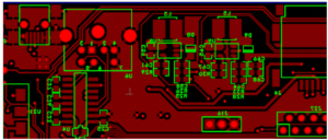
Тогда что такое DFM CHECK? befПеред началом непосредственного процесса сборки производители тщательно проверяют файл проекта печатной платы на предмет функциональности и технологичности. На этом этапе, который мы называем DFM, проверяются проектные характеристики печатной платы и анализируются любые отсутствующие, избыточные или потенциально проблемные элементы. Этот этап помогает выявить ошибки в проекте и позволяет разработчикам незамедлительно устранить все недостатки, что, в свою очередь, обеспечивает успешное производство.
-
Проверка электронных компонентов
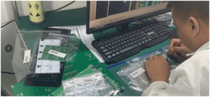
Перед началом сборки компания UETPCB выполнит ещё один этап — проверку компонентов. Наша команда инженеров проверит упаковку компонентов, их номиналы, количество, размеры монтажных площадок, артикулы и т. д. на соответствие спецификации (BOM) и печатной плате. В случае обнаружения каких-либо несоответствий мы уладим все вопросы с заказчиком до начала сборки.
Фактические этапы процесса сборки печатных плат
-
Нанесение паяльной пасты
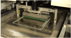
Принтер для нанесения паяльной пасты, предназначенный для нанесения паяльной пасты (смеси мелких зерен припоя с флюсом) с помощью трафарета и ракелей на соответствующие контактные площадки печатных плат.
-
Размещение компонентов
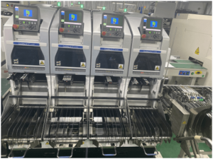
Этот этап процесса сборки печатных плат (PCBA) в настоящее время полностью автоматизирован. Установка таких компонентов, как компоненты поверхностного монтажа, которая раньше выполнялась вручную, теперь осуществляется с помощью роботизированных монтажных машин. Эти машины точно размещают компоненты в заранее запланированных местах на плате.
-
Пайка методом рефлоу
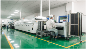
Как только паяльная паста и компоненты для поверхностного монтажа установлены на место, они должны оставаться там. Это означает, что паяльная паста должна затвердеть, прикрепив компоненты к плате. Для этого сборка с паяльной пастой и компонентами на ней проходит по конвейерной ленте, которая движется через промышленную печь для рефлоу-пайки. Нагреватели в печи плавят припой, содержащийся в пасте. После завершения плавления сборка снова перемещается по конвейерной ленте и проходит через ряд охлаждающих нагревателей. Цель этих охладителей — охладить расплавленный припой и довести его до затвердевшего состояния.
-
Проверка
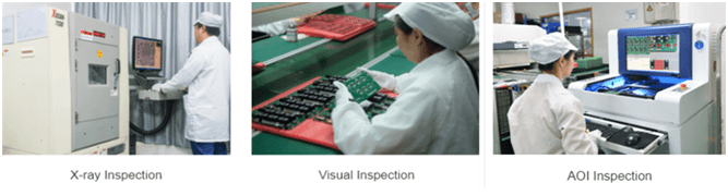
После процесса рефлоу печатная плата проходит контроль на работоспособность. Этот этап позволяет выявить некачественные соединения, неправильно установленные компоненты и короткие замыкания, возникшие в результате последовательного перемещения платы во время процесса рефлоу. Производители печатных плат используют несколько этапов контроля, таких как визуальный осмотр, автоматический оптический контроль и рентгеновский контроль, для проверки работоспособности платы, выявления некачественных паяных соединений и обнаружения любых потенциально скрытых проблем.
-
Установка компонентов с отверстиями
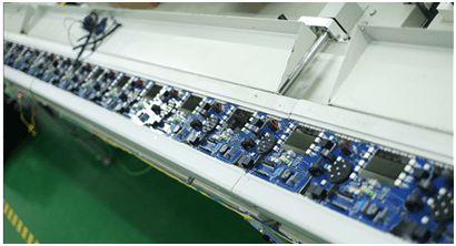
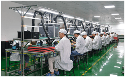
Некоторые типы печатных плат требуют установки компонентов с сквозными отверстиями наряду с обычными компонентами поверхностного монтажа (SMD). Данный этап предназначен именно для установки таких компонентов. Для этого создаются сквозные отверстия с металлическим покрытием, с помощью которых компоненты печатной платы передают сигналы с одной стороны платы на другую. Установка компонентов с сквозными отверстиями на печатной плате обычно осуществляется методом ручной пайки или пайки в волне припоя для достижения требуемых результатов.
-
Окончательная проверка и функциональное тестирование / Программирование ИС
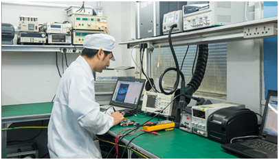
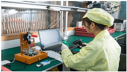
После завершения этапа пайки в процессе сборки печатных плат (PCBA) проводится окончательный контроль, в ходе которого проверяется работоспособность печатной платы. Этот контроль называется “функциональным тестированием”. В ходе теста печатная плата проходит все необходимые испытания, имитирующие нормальные условия её эксплуатации. Во время теста через печатную плату пропускаются питание и имитированные сигналы, а тестировщики контролируют её электрические характеристики.
-
Очистка и упаковка
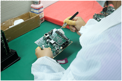
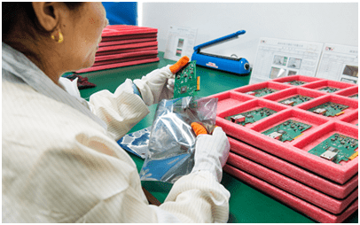
Поскольку в процессе пайки на печатных платах остаётся некоторое количество остатков флюса, перед отправкой готовой платы заказчику крайне важно тщательно очистить сборку. Для этого печатные платы промывают деионизированной водой. После очистки плату тщательно сушат с помощью сжатого воздуха. Теперь сборка печатной платы готова к проверке и осмотру заказчиком.
Испытания на надежность в процессе производства печатных плат
Производство печатных плат (PCBA) ни в коем случае не сводится к простому добавлению закупки материалов к процессу поверхностного монтажа (SMT). Любая проблема с каким-либо материалом повлияет на общий результат изготовления печатной платы, что требует от нас наличия достаточных навыков проверки материалов, управления поставщиками, технического анализа и проведения испытаний на надежность.
Производители печатных плат (PCBA) зачастую игнорируют испытания на надежность, полагая, что если плата PCBA прошла тестирование без проблем, она будет принята конечными потребителями. Однако многие печатные платы PCBA имеют серьезные дефекты, такие как короткий срок службы и нестабильная работа в конечных изделиях, которые возникают из-за того, что предприятия по сборке печатных плат не проводят испытания на надежность в строгом соответствии с требованиями.
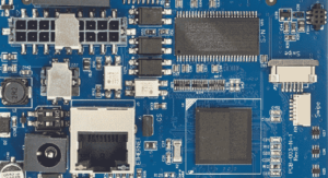
- Функциональное тестирование
Функциональное тестирование используется в качестве заключительного этапа производства печатных плат (PCBA). Оно позволяет определить, прошли ли готовые печатные платы тестирование или нет, и подтвердить отсутствие дефектов в аппаратной части продукции перед отправкой. В ходе тестирования можно проверить работоспособность от 50% до 100% отгружаемой продукции, что позволяет минимизировать затраты времени и усилий со стороны OEM-производителя на проверку и устранение неисправностей.
- Испытания на старение
Печатная плата (PCBA) с подтвержденной работоспособностью была помещена в условия с заданными значениями температуры и влажности, после чего проводились повторные включения и выключения, имитация работы функций, испытания под нагрузкой и т. д. Стабильность печатной платы проверялась в ходе непрерывной работы продолжительностью от 24 до 72 часов. Испытание на старение занимает много времени, что делает невозможным его проведение для крупных партий продукции. На практике испытание на старение проводится только на выборочных образцах, и общий выход данной партии продукции можно определить по проценту отбраковки при выборочном тестировании.
- Испытания на вибрацию
В процессе доставки заказчикам многие печатные платы PCBA часто сталкиваются с проблемами, вызванными вибрацией во время транспортировки, такими как отрыв компонентов и растрескивание контактных площадок. С помощью вибрационных испытаний в лабораторных условиях можно эффективно смоделировать воздействие вибрации, возникающей при транспортировке, и постепенно выявить скрытые недостатки в процессе пайки печатных плат. Это позволяет избежать некачественной пайки в серийных партиях печатных плат с монтажом компонентов (PCBA) и повысить общий выход готовой продукции при поставке.
- Испытания на импульсные перенапряжения
В процессе сборки печатных плат (PCBA) работа при нормальном напряжении зачастую проходит без проблем, однако при определённом скачке напряжения возникает переходная неисправность. Многие схемы не являются идеальными. При их разработке часто не учитывается фатальное воздействие мгновенных скачков напряжения или тока на всю схему, что требует проведения испытаний на перенапряжение перед запуском серийного производства PCBA.
- Испытания упаковки
Этот тест часто упускают из виду, но он может привести к неожиданной проблеме: мы затратили много усилий на то, чтобы сделать печатные платы идеальными, но все пошло наперекосяк на последнем этапе — при упаковке и транспортировке. Поэтому на заводе следует смоделировать форму упаковки печатной платы и провести соответствующее испытание на падение.
2. 5 способов контроля качества печатных плат
Сборка печатных плат также называется PCBA, и процесс изготовления PCBA включает в себя производство печатных плат, закупку и проверку компонентов, монтаж поверхностного монтажа (SMD), монтаж в корпусах DIP, программирование, тестирование, старение и ряд других этапов. Если цепочка поставок и производственная цепочка слишком длинные, это приведет к появлению дефектов на многих платах PCBA. Однако контроль качества процесса сборки печатных плат (PCBA) позволяет избежать большинства неисправностей в готовых платах. Поэтому большинство профессиональных производителей, занимающихся сборкой печатных плат, осуществляют контроль качества процесса сборки печатных плат (PCBA), чтобы гарантировать высокое качество предоставляемых ими услуг по сборке печатных плат (PCBA). Для сборки печатных плат (PCBA) важно наладить контроль качества процесса сборки печатных плат (PCBA), и в данной статье будут представлены некоторые способы обеспечения контроля качества этого процесса.
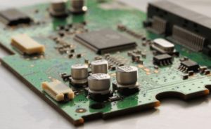
- 1. Производство печатных плат (PCBA)
При производстве печатных плат с монтажом компонентов (PCBA) особенно важно провести предпроизводственное совещание после получения заказа на PCBA. В первую очередь это необходимо для технического анализа файлов Gerber печатных плат и подготовки отчета о технологичности конструкции (DFM) с учетом различных потребностей заказчика. Многие мелкие производители не придают этому должного значения, но, как правило, предпочитают так поступать. Ещё одной важной задачей при производстве PCBA является проверка проекта печатной платы. Являясь основой сборки печатных плат, проект печатной платы определяет качество производства PCBA. Некачественный проект печатной платы не только легко приводит к проблемам с качеством продукции, но и вызывает необходимость в значительных объёмах доработок и ремонтных работ.
- 2. Поиск поставщиков и проверка компонентов для печатных плат
Поставка компонентов в процессе сборки печатных плат (PCBA) также является важной частью контроля качества данного процесса. Каналы поставок компонентов должны подвергаться строгому контролю, а сами компоненты должны закупаться у крупных дистрибьюторов и оригинальных производителей, чтобы избежать использования подержанных и контрафактных материалов. Кроме того, следует организовать специальный пункт проверки PCBA для тщательного контроля следующих элементов с целью обеспечения безотказной работы деталей.
Печатная плата: Проверьте температуру печи для рефлоу-пайки, убедитесь, что отверстия, через которые не проходит проводка, не заблокированы и нет утечки краски, а также проверьте, не деформирована ли поверхность печатной платы и т. д.
IC: Check whether the screen printing and BOM are identical, and carry out constant temperature and humidity preservation.
Other common methods: Check screen printing, appearance, electrical measurement, etc.
- 3. SMT Assembly
Solder paste printing and reflow furnace temperature control system are the key points of PCB assembly (PCBA), which need to use the laser steel stencil which has higher quality requirements and can better meet the processing requirements. According to PCB requirements, part of the need to increase or reduce the stencil’s hole, or U-shaped hole, just according to the process requirements to make the stencil. The temperature control of the reflow oven is very important to the wetting of the solder paste and the solderability of the steel stencil, which can be adjusted according to the normal SOP operating guidelines.
In addition, strict implementation of AOI testing can greatly reduce the adverse effects caused by human factors.
- 4. DIP Process
In the DIP process, the die design for wave soldering is the key. How to use the mold to greatly improve the yield, this is PE engineers must continue to practice and summarize the process.
- 5. PCBA Board Testing
For orders with PCBA (printed circuit board assembly) testing requirements, the main test contents include ICT (In-Circuit Test), FCT (functional test), Life Cycle Testing(aging test), temperature and humidity test, drop test, etc.
3. Краткая проверка и оценка качества печатных плат
4 Steps of Short Checking of Circuit on PCB
Now you know the process of PCB assembly (PCBA), and how to control the quality of PCBA. After PCB fabrication and assembly, checking short and identify the quality of PCB assembly (PCBA) products can help you avoid defects during the PCBA process, and make PCB manufacturing and assembly better.
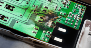
Step 1: How to Find A Short Circuit in A PCB?
Visual Inspection
The first step is to examine the entire surface of the PCB. If so, use a magnifying glass or low-power microscope. Cracks or spots in any solder should be noted. Check all through holes. If none-plated through holes are specified, make sure this is the case on the board. Poor plating through holes can cause a short circuit between layers and cause everything you have to ground, VCC or both together.
If the short circuit is really serious and causes the component to reach a critical temperature, you will actually see burn spots on the printed circuit board. They may be small, but they will turn brown instead of the normal green solder. If you have multiple boards, a burned PCB can help you narrow down the area in a particular location without having to power another board, sacrificing the search area. Unfortunately, there were no burns on the circuit board itself, just unlucky fingers checking to see if the IC was overheating.
Some short circuits will occur inside the circuit board and will not produce a burn spots. This also means that they will not be noticed from the surface. Here, you will need other methods to detect short circuits in the PCB.
Infrared Imaging
Using an infrared thermograph can help you locate areas that generate a lot of heat. If an active component is not seen away from a hot spot, a PCB short circuit may occur even if the short circuit occurs between the inner layers.
Short circuits usually have a higher resistance than normal wiring or solder pads because they have no benefit of optimization in the design (unless you really want to ignore rule checking).This resistance, along with the naturally high current generated by the direct connection between the power supply and the ground, means that the conductor in the short circuit of the PCB will heat up. Start with the lowest current you can use. Ideally, you would see a short circuit and then cause more damage.
Step 2: How to Test The Short Circuit on The PCB Board
In addition to the first step of checking a circuit board with a trusted eye, there are several other ways you can find the potential cause of a PCB short circuit.
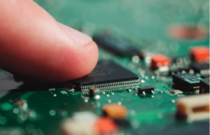
Test with A Digital Multimeter
To test the circuit board if short circuit or not, you need to check the resistors between the different pads in the circuit. If the visual inspection does not reveal any clues as to the location or cause of the short circuit, grab the multimeter and try to trace the physical location on the printed circuit board. The multimeter approach has received mixed reviews in most electronic forums, but tracking test points can help you figure out what the problem is.
You will need a very good multimeter with good sensitivity, which is easiest if it has a buzzer function to alert you when short circuits are detected. For example, if the resistors between adjacent wires or pads on a PCB is measured, high resistors should be measured.
If the resistor between the two conductors to be measured in a separate circuit is very low, the two conductors may be bridged either internally or externally. Note that bridging two adjacent wires or pads with an inductor (for example, in an impedance matching network or discrete filter circuit) will result in very low resistance readings because the inductor is just a coil conductor. However, if the two conductors on the board are far apart and the resistance you read is small, there will be a bridge somewhere on the board
Tests Relative to The Ground
Particularly importance are short circuits involving ground through-holes or connecting formations. A multilayer PCB with an internal layer will include a return path through the assembly near the through-hole, which provides a convenient location for checking all other through-holes and pads on the board surface layer. Place one probe on the ground connection and touch the other probe on the other conductors.
The same ground connection will also exist at other locations on the board, meaning that if each probe is touched to two different grounding through-holes, the reading will be small. Pay attention to the layout when doing this, because you don’t want to mistake a short circuit for a common ground connection. All other ungrounded bare conductors shall have a high resistance between the common ground connection and the conductor itself. If the value read is low and there is no inductor between the conductor in question and the ground, the component may be damaged or short circuited.
Short Circuit Components
Checking for short circuits in components also involves measuring resistors using a multimeter. If visual inspection does not reveal excess solder or sheet metal between the pads, a short circuit may be formed in the inner layer between the pads/pins on the assembly. A short circuit may occur between the pads/pins on the assembly due to poor soldering. This is one of the reasons PCB should undergo DFM and design rule checks. Close soldering and perforations may short-circuit accidentally during manufacturing.
Here, you need to measure the resistance between the pins on the IC or connector. Adjacent pins are particularly easy to short circuits, but these are not the only places where short circuits can occur. Check that the resistances between the pads/pins are relative to each other and that the ground connection has low resistance.
Narrow Location
If you think there is a short circuit between two conductors or between one conductor and the ground, you can narrow the position by checking nearby conductors. Connect one wire of the multimeter to a suspiciously short circuit connection, move another wire to a nearby different ground connection, and check the resistance. As you move further to the ground, you should see a change in resistance. If the resistance is increased, you are removing the grounding wire from the short circuit position. This helps you narrow down the exact location of the short circuit, even to a specific pair of pads/pins on the component.
Step 3: How to Find Faulty Components on A PCB?
A faulty component or improperly installed component can be part of a short circuit that causes many problems on the circuit board. Your components may be defective or forged, causing a short circuit or short-circuit phenomenon.

Adverse Element
Some components deteriorate, such as electrolytic capacitors. If you have suspect components, check those components first. If you’re not sure, you can often do a quick Google search for components that you suspect are “failing” to find out if this is a common problem. If you measure a very low resistance between the two pads/pins (neither of which are ground or power pins), a burnt component may cause a short circuit. This is a clear indication that the capacitor is broken. The capacitor also bulges if it goes bad or if the voltage applied exceeds the breakdown threshold.
Step 4: How to Test The PCB Destructively?
Destructive testing is obviously a last resort. If you can use an X-ray imaging device, you can examine the inside of the circuit board without breaking it.
In the absence of X-ray devices, you can begin to remove components and run the multimeter tests again. This helps in two ways. First, it gives you easier access to pads (including thermal pads) that may short-circuit. Second, it eliminates the possibility of short-circuiting the faulty component, allowing you to focus on the conductor. If you try to narrow down the short circuit to the connection on the component, such as between two pads, it may not be clear whether the component is defective or if there is a short circuit inside the circuit board. At this point, you may need to remove the component and check the solder pad on the board. Unmounting the component allows you to test whether the component itself is defective or whether the solder pad on the board is bridged internally.
If the location of the short circuit (or possibly multiple short circuits) remains elusive, you can cut through the circuit board and try to narrow the short circuit. If you are familiar with the general location of the short circuit, you can cut a section of the circuit board and repeat the multimeter test on that section. At this point, you can repeat the above tests with a multimeter to check for short circuits at a particular location. If you’ve reached this point, your shorts have been particularly elusive. This will at least allow you to narrow the short circuit to a specific area of the circuit board.
2 Aspects for Quality Identify of PCB Board?
In order to enhance the core competitiveness, more and more manufacturers monopolize the market with low prices. but these ultra-low prices are achieved by reducing the cost of materials and process, which makes PCB prone to cracks, scratches, and its precision, performance and other comprehensive factors are not up to the standard, which will seriously affect the solderability and reliability of the product, etc. In the face of various PCB boards on the market, the quality of PCB boards can be identified from two ways: the first way is to distinguish and identify from the appearance; the other is to identify from the quality specification requirements of the PCB board itself.
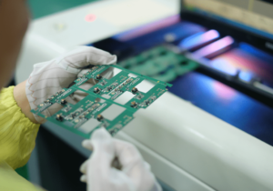
Distinguish The Quality of The Circuit Board from The Appearance
Generally, the appearance of PCB board can be analyzed and identified from three ways:
- a) Standard rules for size and thickness
The thickness of the PCB board to the standard circuit board is different size, customers can measure and check according to their own product thickness and specifications.
- b) Gloss and color
The external PCB board is covered with ink, the circuit board can play the role of insulation, if the color of the board is not bright, less ink, insulation board itself is not good.
- c) weld appearance
PCB board due to many parts, if the soldering is not good, components easy to fall off the PCB board, seriously affect the soldering quality of the PCB board, good appearance, careful identification is very important
High Quality PCB Circuit Board Should Meet The Following Requirements:
a)After the components are installed, the board should be good working, that is, the electrical connection should meet the requirements;
- b) The line width, line thickness and line spacing shall meet the requirements to avoid line heating, circuit opening and short circuit.
- c) High temperature coppers is not easy to fall off;
d)The surface of copper is not easy to oxidize, which affects the assembly speed. it soon goes bad after oxidation
- e) No additional electromagnetic radiation
- f) The shape is not deformed, so as to avoid deformation of shell and dislocation of screw hole after installation. Now it is all mechanized assembly, the hole position of PCB board and the distortion error of lines and design should be within the allowed tolerance range.
- g) High temperature, high humidity and special environment should also be considered.
- h) The mechanical properties of the surface shall conform to the assembly requirements.
4. Конформное покрытие
Conformal coating also seen as PCB coating is a PCB assembly (PCBA) process which aims to protect the final PCBA products from nature damage and become more durable. Typically , the conformal coating material is thin polymeric film. The PCB assembly (PCBA) products which are processed by conformal coating can resistant some environmental factors, such as moisture, dust, salt, chemicals, temperature changes, etc.
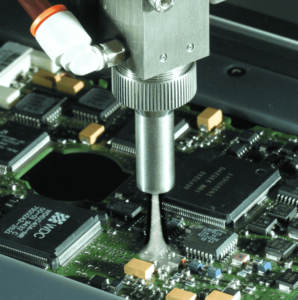
Requirements for Conformal Coating:
- A) Conformal coating thickness: coating film thickness control in 0.05mm-0.15mm.Dry film thickness 25um-40um
B)Secondary coating: In order to ensure the thickness of products with high protection requirements, secondary coating can be carried out after the film is fixed (whether to carry out secondary coating according to the demand shall be determined)
C)Check and repair: visually check whether the coated circuit board meets the quality requirements, and repair the problems. For example: DIP parts needle and other protection area touch coating, usable forceps clip depilate cotton ball or clean cotton ball dips in to wash board water to scrub its clean, pay attention to cannot wash off normal coating when swabbing. - D) Replacement of components: After the curing of the coating, if you want to replace components, you can follow the following operation
a, Directly solder the components with ferrochrome.
b, Soldering alternative components
c, Use a brush dipped in conformal coating and brush coating on alternative components, and make the coating film side dry curing
Operation Requirements:
- A) Conformal coating workplace requirements clean, no dust flying, must have good ventilation measures, and prohibit the entry of irrelevant personnel
- B) Wear a mask or gas mask, rubber gloves, chemical protective glasses and other protective equipment during operation to avoid injury to the body
- C) After the completion of the work, the used tools should be cleaned in a timely, and the container with conformal coating should be closed and sealed tightly
- D) The circuit board should be done anti-static measures, not the circuit board overlap placed, coated process, the circuit board should be placed horizontally
Quality Requirements:
- A) The surface of the circuit board cannot be flow coating, drip leakage phenomenon, brush coating pay attention to not drip to the local isolation part
B)The conformal coating side shall be flat, bright, thin and uniform, Need the solder pads, SMT component or conductor shall be well protected
C) The surface and components of the coating can not have bubbles, pinholes, ripples, shrinkage, dust and other defects and foreign substances, no powder, no peeling phenomenon, Note: the coating film have not dry before do not touch the coating film
D) local isolation of the components or areas can not be coated with conformal coating
E) Areas and components that cannot be coated with conformal coating:
a, routine not coated components: High-power radiator, heat sink, power resistors, high power diode, cement resistors, dialing switch, potentiometer (adjustable resistor), buzzer, battery holder, fuse holder, IC socket, light touch switch, relay, such as the type of socket, pin header, terminals and the DB9, DIP or SMD type light emitting diode (Non-indicating effect), digital tube, grounding screw holes
b, Areas and components that are not allowed to use the coating as specified in the drawing
c, According to the provisions in the details of “Non-coating components( Areas) catalog”, the components with conformal coating cannot be used
- If the conventional non-coated components need to be coated, the R&D department may specify requirements or the drawings may be marked for anti-coating to be coated.
5. Оценка производителя печатных плат
It’s a tough job for OEMs to settle on a long-term PCB fabricator or assembler (we’ll call them PCB Houses in the following paragraphs) since the globe is flooded with too many PCB services providers. This article brings some guidelines on how to picking up the perfect fit PCB Houses from your long waiting list. In addition, a FREE template investigation list will be supplied so that you can directly make use of it as a standard when you evaluate a PCB House to build long-term cooperation.
Though PCB manufacturing and assembly contain so many links that should be carefully inspected one by one, the process mainly centers on Products, Capabilities and Service. As a result, this article follows the same route.
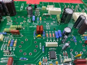
Products
The quality of printed circuit boards will directly affect your final products’ application and performance. Hence, the priority principle of evaluating PCB Houses is to check their products situation, which can be expanded in three aspects: Quality, Industries and Cost.
1). Quality
Everyone is eager for high quality deriving from the following aspects:
• Whether SPC such as Cpk control of components or manufacturing administration diagram has been applied during PCB manufacturing process;
• Whether constant quality administration improvement such as QCC or TQM has been implemented;
• Whether Administration of ECO (Engineering Change Order) is applied;
• Whether there’s component waive control principles published in their terms and conditions;
• Do they conform to stringent quality control evaluations including Material inspection record and administration, SMT yield rate, AQL level, File administration, BOM preservation, ESD implementation, Equipment calibration;
2). Industries
Printed circuit boards are applied in so many different industries, specific industry has strict and special requirements on its manufacturing standards. It’s almost impossible for one PCB House to cover all industries evenly. Generally, they tend to be more proficient in serving certain industries while not so excellent for other industries. For example, PCB Houses proficient in processing PCBs for mobile phones surely have sufficient experience to constrain space in end products, PCB Houses mainly serving for space industries perform definitely better in high density.
Under this condition, you have to be fully aware of industries your investigated PCB Houses good at dealing with so that you’ll cooperate with a professional partner instead of a cure-all partner.
3). Cost
In spite of tips leading to cost reduction in PCB assembly (PCBA), prices are sometimes a major element driving our final decision. As a necessary consideration when selecting a PCB House, cost should be analyzed from two aspects:
• Integral quotation – Do not be addicted in the attractive figure alone. Reliable PCB Houses are responsible in each word they claim. You should make sure the price their salesperson gives you is a complete price without any hidden or extra money in the later period of your order;
• Constant cost reduction – It refers to some discounts in your reorders. Although a PCB House will never provide you with always-low prices, you can expect a constant discount in your reorder such as free from tooling cost etc. This strategy is the solid foundation for a long-term cooperation;
Возможности
As mentioned above, product quality is the soul for a PCB House who depends on its capabilities. PCB manufacturing and assembly capabilities can be displayed in the following aspects:
1). Certificates
Certificates stand for the House’s genuine manufacturing capabilities. When cooperating with PCB Houses certificated with ISO9001:2008, UL, RoHS, etc. standards, you can rest assured that they will strictly stick to the regulations of those certificates to obtain a high quality in their products.
2). Technology
Aspects concerning an investigated PCB House’s technology can be summarized into the following items:
• Whether technology it applies caters to your requirement and processing capabilities reach your requirement;
• Whether advancing equipment for processing or automation is owned in their house;
• Whether they perform creatively on technologies;
• Whether it is capable of leading in new processing method in the market;
• Processing capability evaluation;
• BGA IC repair capability;
• Soldering capability of 0201 or 01005 and repair capability;
• RoHS implementing capabilities;
• SOP integrity;
• How to set back mistaken material selection and negative polarity;
• Capability of reviewing circuit and providing DFM service;
• Moisture Sensitivity Level (MSL) component control capabilities;
• Solder paste temperature returning, sealing off and storage life administration capabilities;
• De-panel processing capabilities;
Why Choose Chinese PCB Assembly Company?
As the development of the technology of PCB fabrication and assembly, Chinese PCB assembly companies have become more competitive. The large PCB market value promote Chinese PCB assembly (PCBA) industry. Nowadays, Chinese PCB assembly companies equip advanced PCB manufacturing and assembly technology and provide high-quality PCB assembly (PCBA) service with affordable price.
As a professional PCB assembly company, UETPCB has more than 15 years in this industry, and has equipped a complete PCB assembly service system. Our service is PCB fabrication and assembly, mainly includes prototype PCB, turnkey PCB assembly, and other relative services.
Click here and know more about PCB manufacturing and PCB assembly (PCBA) service.
- Printed Circuit Board Assembly Basics
- What Is SMT Assembly
- What You Need to Know About PCB Manufacturing and PCB Assembly