
There are some important steps you can take to check for short circuits in your PCB:
Step 1: How to find a short circuit board in PCB?
Step 2: How to Check Short Circuit board in PCB?
Step 3: How to find faulty components on a PCB?
Step 4: How to test the PCB destructively?
Step 1: How to find a pcb short circuit?
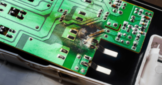
Visuele inspectie
The first step is to examine the entire surface of the pcb short circuit. If so, use a magnifying glass or low-power microscope. Cracks or spots in any solder should be noted. Check all through holes. If none-plated through holes are specified, make sure this is the case on the board. Poor plating through holes can cause a pcb short circuit between layers and cause everything you have to ground, VCC or both together.
If the pcb short circuit is really serious and causes the component to reach a critical temperature. You will actually see burn spots on the printed circuit board. They may be small, but they will turn brown instead of the normal green solder.
If you have multiple boards, a burned PCB can help you narrow down the area in a particular location without having to power another board, sacrificing the search area. Unfortunately, there were no burns on the circuit board itself, just unlucky fingers checking to see if the IC was overheating.
Some pcb short circuits will occur inside the circuit board and will not produce a burn spot. This also means that they will not be noticed from the surface. Here, you will need other methods to detect short circuits board.
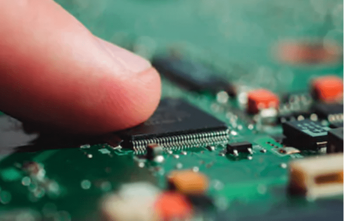
Infraroodbeeldvorming
Met behulp van een infraroodthermograaf kunt u plekken opsporen die veel warmte afgeven. Als er geen actief onderdeel te zien is buiten een warmtepunt, kan er een kortsluiting in de printplaat ontstaan, zelfs als de kortsluiting zich tussen de binnenste lagen voordoet.
Pcb Short circuits usually have a higher resistance than normal wiring or solder pads because they have no benefit of optimization in the design (unless you really want to ignore rule checking).This resistance, along with the naturally high current generated by the direct connection between the power supply and the ground, means that the conductor in the short circuit of the PCB will heat up. Start with the lowest current you can use. Ideally, you would see a pcb short circuit and then cause more damage.
Step 2: How to test the short circuit in PCB board?
Naast de eerste stap, namelijk het met een geoefend oog controleren van een printplaat, zijn er nog verschillende andere manieren om de mogelijke oorzaak van een kortsluiting in een printplaat op te sporen.
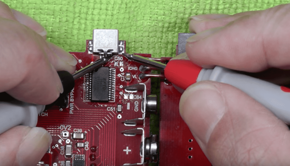
Test pcb short circuit with a digital multimeter
To test the circuit board is a short circuit board or not. You need to check the resistors between the different pads in the circuit. If the visual inspection does not reveal any clues as to the location or cause of the short circuit board, grab the multimeter and try to trace the physical location on the pcb short circuit. The multimeter approach has received mixed reviews in most electronic forums. But tracking test points can help you figure out what the problem is.
You will need a very good multimeter with good sensitivity, which is easiest if it has a buzzer function to alert you when pcb short circuits are detected. For example, if the resistors between adjacent wires or pads on a PCB are measured, high resistors should be measured.
Als de weerstand tussen de twee te meten geleiders in een afzonderlijk circuit zeer laag is, kunnen de twee geleiders intern of extern worden overbrugd. Houd er rekening mee dat het overbruggen van twee aangrenzende draden of pads met een spoel (bijvoorbeeld in een impedantie-aanpassingsnetwerk of een discreet filtercircuit) zal leiden tot zeer lage weerstandswaarden, omdat de spoel in feite slechts een spoelgeleider is. Als de twee geleiders op de printplaat echter ver uit elkaar liggen en de gemeten weerstand klein is, zal er ergens op de printplaat een brug zijn.

Tests short circuit board relative to the ground
Particularly important is short circuits involving ground through-holes or connecting formations. A multilayer PCB with an internal layer will include a return path through the assembly near the through-hole, which provides a convenient location for checking all other through-holes and pads on the board surface layer. Place one probe on the ground connection and touch the other probe on the other conductors.
The same ground connection will also exist at other locations on the board, meaning that if each probe is touched to two different grounding through-holes, the reading will be small. Pay attention to the layout when doing this, because you don’t want to mistake a pcb short circuit for a common ground connection. All other ungrounded bare conductors shall have a high resistance between the common ground connection and the conductor itself. If the value read is low and there is no inductor between the conductor in question and the ground, the component may be damaged or pcb short circuited.
Pcb short circuit components
Checking for pcb short circuits in components also involves measuring resistors using a multimeter. If a visual inspection does not reveal excess solder or sheet metal between the pads, a pcb short circuit may be formed in the inner layer between the pads/pins on the assembly. A short circuit may occur between the pads/pins on the assembly due to poor soldering. This is one of the reasons PCB should undergo DFM and design rule checks. Close soldering and perforations may short-circuit accidentally during manufacturing.
Here, you need to measure the resistance between the pins on the IC or connector. Adjacent pins are particularly easy to pcb short circuits, but these are not the only places where short circuits can occur. Check that the resistance between the pads/pins are relative to each other and that the ground connection has low resistance.
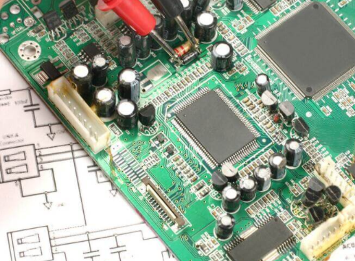
Narrow location
If you think there is a short circuit between two conductors or between one conductor and the ground, you can narrow the position by checking nearby conductors. Connect one wire of the multimeter to a suspiciously pcb short circuit connection, move another wire to a nearby different ground connection, and check the resistance. As you move further to the ground, you should see a change in resistance. If the resistance is increased, you are removing the grounding wire from the pcb short circuit position. This helps you narrow down the exact location of the short circuit, even to a specific pair of pads/pins on the component.
Step 3: How to find faulty components on a PCB?
A faulty component or improperly installed component can be part of a pcb short circuit that causes many problems on the circuit board. Your components may be defective or forged, causing a short circuit or short-circuit phenomenon.
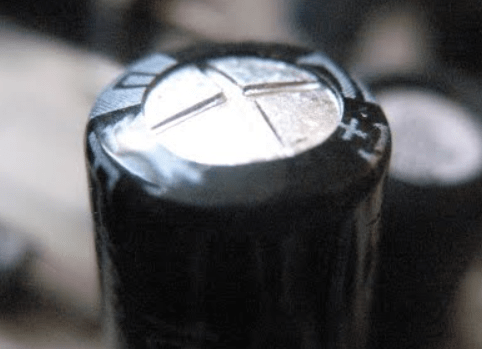
Adverse element
Some components deteriorate, such as electrolytic capacitors. If you have suspect components, check those components first. If you’re not sure, you can often do a quick Google search for components that you suspect are “failing” to find out if this is a common problem. If you measure a very low resistance between the two pads/pins (neither of which are ground or power pins), a burnt component may cause a pcb short circuit. This is a clear indication that the capacitor is broken. The capacitor also bulges if it goes bad or if the voltage applied exceeds the breakdown threshold.
Step 4: How to test the PCB destructively?
Destructief onderzoek is uiteraard een laatste redmiddel. Als je een röntgenapparaat kunt gebruiken, kun je de binnenkant van de printplaat onderzoeken zonder deze te beschadigen.
Als er geen röntgenapparatuur beschikbaar is, kun je beginnen met het verwijderen van componenten en de multimetertests opnieuw uitvoeren. Dit helpt op twee manieren. Ten eerste krijg je zo gemakkelijker toegang tot pads (inclusief thermische pads) die mogelijk kortsluiting veroorzaken. Ten tweede voorkomt het de kans op kortsluiting in de defecte component, waardoor u zich kunt concentreren op de geleider. Als u probeert de kortsluiting te lokaliseren bij de aansluiting op de component, bijvoorbeeld tussen twee pads, is het mogelijk niet duidelijk of de component defect is of dat er een kortsluiting in de printplaat zit. Op dat moment moet je de component wellicht verwijderen en het soldeerpad op de printplaat controleren. Door de component te demonteren, kun je testen of de component zelf defect is of dat het soldeerpad op de printplaat intern is overbrugd.
If the location of the short circuit board(or possibly multiple short circuits) remains elusive, you can cut through the circuit board and try to narrow the pcb short circuit. If you are familiar with the general location of the short circuit, you can cut a section of the circuit board and repeat the multimeter test on that section. At this point, you can repeat the above tests with a multimeter to check for pcb short circuits at a particular location. If you’ve reached this point, your shorts have been particularly elusive. This will at least allow you to narrow the short circuit board to a specific area of the circuit board.