
andUSB is the most widely used port we need every day. Need to recharge your mobile battery? You need a charger with a USB Lightning, micro-A, micro-B, or USB-C port. Need to transfer data to your computer? You need a USB cable to do so. In almost every electronics project, we need a USB port to transfer data or power. Here, the USB pinout is crucial.
The USB pinout directly affects the device’s overall performance. For example, the performance of USB 3.0 cannot be the same as that of USB 2.0. Also, USB Type A is structurally different from USB Type B or C. With the development of modern electronics, various types of USB ports have emerged.
When designing the USB pinout, you must be careful with the layout, wiring, and routing. A minor mistake in the pin configuration may cause connection errors. Therefore, proper pin arrangement is critical during PCB design.
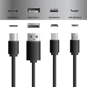
When you try to design the PCB for the USB Pinout, you will find various connector types. Some common ones are USB A, B, C, micro, and mini, among others. Each of these types has its own pinout structure. Besides, each serves a specific purpose and application.
This article will give you an idea of how to start your PCB design project for the USB pinout. We will explore more about the layout, wiring, and routing to ensure signal integrity and power delivery.
Understanding USB Pinout
Did you ever think about what leads us to invent USB cables and USB pinouts? The need for a universal peripheral interface drives us here. The goal was to create a single USB cable pinout that delivers reliable, fast power and data.
A pinout structure combines multiple pins to serve specific requirements. Additionally, it indicates how the power and data supplies are distributed between a host (such as a computer) and a peripheral device (such as a printer or mouse).
There are various USB pinouts available on the market. For example, USB 3.0/3.1 Type-A/B, Micro-USB, Mini-USB Pinout, and USB Type-C. As technologies advance, new miniaturized solutions are emerging. They are used in almost all smart devices worldwide to transfer data and deliver power.
USB Data Transfer
To transfer data, a USB uses differential signaling. In this process, data transmission occurs on the D+ and D- wires simultaneously. The voltage difference between D+ and D- represents the binary 1 and 0. Thus, it easily cancels electrical noise while ensuring fast data transfer between the host and peripheral device.
USB Power Delivery
There are a few standard USB cable pinouts that provide 5 volts across VBUS and GND. Then, the power flows from the host device to the peripheral device. Traditional types like USB 2.0 typically deliver 500 mA and 2.5 watts of power. On the other hand, newer USBs can provide more power depending on their design.
USB Pinout Types and Their Applications
There’s always a growing need for new products in the electronics industry. Over time, this need led to different USB pinouts. As devices get smaller, faster, and more powerful, new USB designs come out. The latest item offers better performance and faster speed.
USB A Pinout
The USB-A pinout is the most common and traditional connector. It is widely used in computers, chargers, and many electronic devices. It has a flat and rectangular shape. Initially, it was used for host-side connections such as PCs, chargers, and hubs.
The USB-A pinout uses a simple 4-pin configuration. Pin 1 for transferring power (VBUS), pin 2 and 3 help to transmit data (D- and D+), and lastly pin 4 for ground (GND).
USB-A connectors have been widely used since the late 1990s. However, their use has decreased as more minor, reversible connectors like USB-C have emerged. It is typically a unidirectional USB. Their primary applications for host devices include keyboards, mice, flash drives, smart TVs, and more.
The main limitation of this type is its size. It is comparatively larger and has a minimal data transfer capability. Most USB-A ports support 480 Mbps on USB 2.0 devices. Besides, it also doesn’t support fast charging or fast data transfer.
USB B Pinout
The USB B pinout is known for its distinct, slightly square shape with beveled corners. It was introduced in 1996 and is considered traditional, an older type of USB. Later, replaced by mini- and micro-B USB pinouts.
Similar to type A, it has four pins (VBUS, D-, D+, and GND). But the USB 3.0 pinout and later versions have 9 pins, with an additional 5 for faster data transfer.
The difference between Type A and Type B is that Type B is used in peripheral devices, while Type A is used in host devices. So, the Type B pinout is an input port on a device. Their Common applications in devices include printers, scanners, hard drives, and audio systems.
The USB B pinout is also large and supports real-world data transfer rates of 400-450 MB/s in USB 3.0. At the same time, the theoretical value was 625 MB/s.
Micro USB Pinout
Modern-day devices limit types A and B. This is where micro-USB comes into its own, overcoming limitations. It is a smaller, more compact successor to Mini USB designed for use in thin and portable devices.
It has a 5-pin layout, VBUS, D-, D+, GND, and an extra ID pin. The ID pin works with On-The-Go (OTG). Thus, it determines if the device acts as a host or a peripheral. This USB connector is used in smart devices such as tablets, mobile phones, earphones, and more.
Mini USB Pinout
The Mini USB pinout was the first miniaturized USB after the Type A and Type B USB pinouts. In the early 2000s, this USB was widely used in electronic devices.
Similar to micro-USB, it has 5 pins, with an additional ID pin. The ID pin typically supports OTG functionality and defines the device’s role. Thus, its USB cable pinout’s primary applications include older cameras, mobile devices, and music systems such as MP3 players.
USB-C Pinout
The USB Type-C is the newest, most versatile, and smallest USB cable. Its versatility stems from its data transfer speed, video capabilities, and power delivery.
This USB-C Type pinout has an oval shape and a reversible design, containing a 24-pin layout. It has multiple pairs of pins for fast data transfer, as well as several pins for VBUS and GND. Additionally, it has CC pins for role and orientation detection. Its use is nearly ubiquitous in all modern electronics, including laptops, smartphones, and monitors.
PCB Design for USB Pinout
Designing a PCB for a USB pinout needs attention to detail. The layout, wiring, and routing all affect how well data and power flow through the circuit. You must ensure that you have considered all the necessary design factors. This way, you can get stable device performance. It’s basically the foundation of reliable USB communication.
Layout Requirements
A good layout is always necessary for a stable USB pinout design. The biggest threat here is signal interference or data loss. These situations might occur due to poor trace routing or improper grounding. It may also happen due to long differential lines. Besides, excess heat or EM noise can also weaken the signal. Eventually, it causes unstable connections or slower data transfer.
When working with USB pinout PCB layout, pay attention to the following key points:
- Place the USB connector near the board edge for convenient connection.
- Try to keep the ESD protection and common mode inductors close to the USB port.
- Arrange the offer as ESD, then common-mode inductors, and then the RC circuit.
- Try to maintain a safe gap between ESP components and the USB connectors.
- Consider space for post-soldering or assembly needs.
- Keep differential signal lines short and closely matched in length.
- Try to avoid unnecessary bends or vias in traces. It can help you maintain signal quality.
Wiring or Routing Design Requirements
Proper wiring is also crucial to ensuring proper design layout. The goal is to keep signals clean and balanced. You must ensure that everything that affects signal quality is interference-free. Good wiring also maintains impedance and prevents reflection. Overall, it provides smooth data transmission.
When working with wiring requirements, pay attention to the following criteria:
- Use differential wiring for USB signal lines.
- Keep the impedance at 90 ohms and include proper grounding.
- Limit the total trace length to within 1800 mil for the best performance.
- Keep traces as short and direct as possible. It is especially necessary for high-speed USB lines.
- Try to minimize vias during routing. It will avoid impedance changes and signal loss.
- When a via is needed, don’t forget to add a nearby ground via. It will maintain signal return paths.
- Maintain at least 2 mm of spacing between protective ground and main GND.
- Place multiple holes in the ground area. It will ensure strong mechanical and electrical connections.
- Ensure equal-length differential pairs. Try to keep the length difference within 5 mils. It will prevent timing errors.
USB 2.0 Pinout vs USB 3.0 Pinout: What’s the Difference?
Both USB 2.0 and USB 3.0 are widely used today. However, the use cases for USB 3.0 are growing faster than those for USB 2.0.
USB 2.0 is widely used for keyboards, mice, and printers. It is reliable, low-cost, and offers speeds of around 480 Mbps. On the other hand, USB 3.0 can deliver up to 5 Gbps. It also excels at high-bandwidth tasks such as external SSDs, HD webcams, and fast data backup. Mostly, it is used for data transfer. Let’s compare these two technologies in the table below.
| Parameter | USB 2.0 | USB 3.0 |
| Trace Impedance | Differential: 90 ohms ±10% | Differential: 90 ohms ±10% |
| Maximum Differential Internal Delay | Less than 20 mil | Less than 6 mil |
| Trace Length | Up to 6000 mil | Up to 6000 mil |
| Allowed Number of Vias per Signal | Recommended: ≤4; Must not exceed: 6 | Recommended: ≤2; Must not exceed: 1 (0201 package: ≤2) |
| Capacitance Requirements | Not specified | ≤100 nF |
| Differential Pair Spacing | Not specified | Recommended: ≥4× USB line width |
| USB-to-Other Signal Spacing | Not specified | Recommended: ≥4× USB line width |
Get a Quick Quote
Looking for custom or standard PCB design, manufacturing, and assembly services? Reach out to our customer support team for more help. We are an in-house production facility. We make various types of PCBs for electronics. UETPCB also offers a wide range of assembly services. Contact us today and get your quick quote.