
Most modern electronic devices rely on signal regulation to work correctly. You may think of audio amplifiers, power amplifiers, motor controllers, and many sensor modules. On a PCB, even a small change in voltage can affect performance. That is why you need to include adjustable components to fine-tune signals during setup. A proper potentiometer wiring, in this case, plays a crucial role.
A potentiometer is easy to understand, connect, and cost-effective. With correct pot wiring, you can adjust output voltage, set reference levels, and calibrate the circuit directly on the PCB. However, if you choose the wrong pot, it may lead to noise, instability, or even component damage.
Therefore, understanding how a potentiometer works and how it is wired is critical. It is the first step to selecting the most suitable potentiometer for your project.
What is a Potentiometer and How Does it Work?
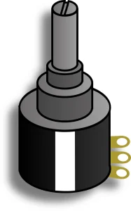
A potentiometer, often called a “pot,” is an electrical device that acts as a variable resistor. It has three terminals and is used to adjust electrical signals. A potentiometer also contains a track and a sliding knob or wiper. You can move the wiper along the track, which will change the resistance.
Typically, it works like a voltage divider. When you apply voltage across its two terminals, the middle terminal taps off a portion of the voltage depending on its position. It lets you control things like volume, brightness, and so on.
Potentiometer Symbol
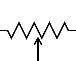
In circuit symbols, a potentiometer has two types, depending on the region.
- ANSI (ZIG-ZAG): A jagged line pointing an arrow to the center, commonly used in North America.
- IEC (Rectangle): A rectangular box with an arrow pointing to the center. It is common in Europe and international standards.
Potentiometer Pinout
A standard potentiometer typically has three pot terminals. Here is the potentiometer pin configuration.
- Pin 1: Terminal A is connected to one end of the resistive track and is linked to VCC (positive voltage).
- Pin 2: It’s the wiper terminal that moves along the resistive track and can adjust the voltage output based on the varying resistance.
- Pin 3: Terminal B is usually connected to the ground (0V).
Wide Applications of Potentiometer and Circuitry
A potentiometer has a wide variety of applications in countless devices. Typical applications include audio volume control, light dimming, or motor speed control. You can also use it as a position sensor in joysticks. Proper potentiometer wiring allows these parts to act as either a voltage divider or a simple variable resistor.
How to Choose the Most Suitable Potentiometer for Your Project?
When choosing a suitable potentiometer for your project, you must know what your project needs. You must carefully assess each required parameter to ensure the device’s stable performance. The following six factors are often needed in the selection process. We recommend that you carefully consider each parameter below.
Required Resistance
Resistance is the circuit’s property of opposition to current flow. It determines how much current flows through a circuit or how voltage is divided. So, choose a value that meets your circuit’s design calculations. For microcontrollers, usually a 10kΩ pot is better. It provides clean signals without wasting battery power.
Tolerance
Tolerance shows a difference between the actual and the rated resistance. The standard tolerance for a potentiometer is 20%. It means a 100kΩ pot might show 80kΩ or 120kΩ resistance readings. Always choose a lower tolerance potentiometer wiring, like 5% or 1%. It offers the best precision and accuracy.
Power Rating
The power rating indicates how much heat the pot can withstand. Small pots are typically rated for 0.1 to 0.5 watts. If your circuit carries high current, the pot may overheat and wear out. To avoid such problems, always calculate power requirements and use a heavy-duty rheostat to handle overload.
Project Required Size
The project’s required size refers to the pot’s physical dimensions. It’s a significant concern for your enclosure and PCB. Check the available space of the PCB panel. Another critical issue is the length and its mounting type. Ensure the length meets your knob size, and the mounting matches your panel. Above all, choose a user-friendly size.
Types of Potentiometer
Different electronic projects have different control needs. Some require smooth linear adjustment, while others follow perception or need compact tuning. As a result, pots and pot pinouts come in various types, too. Size accuracy, adjustment method, and control UI all affect the design.
#1 Linear Potentiometer
A linear potentiometer is one of the most common types of pots. It has a direct proportional relation with resistance and the wiper. For example, if you turn the wiper halfway, you will get 50% of the total resistance properly. Typical applications are sound control and sensors.
Linear pots are used as voltage dividers with a voltage output. Potentiometer wiring is:
- Pin 1: It connects with the positive voltage terminal (VCC).
- Pin 2: Wiper terminal varies the voltage based on its position.
- Pin 3: Connected with the GND.
#2 Logarithmic Potentiometer
Logarithmic potentiometer, also known as “audio taper”. First, it changes resistance slowly, then changes it abruptly. This system is designed to control sound and make it shift logarithmically, as human hearing is logarithmic.
Logarithmic Potentiometer Wiring for Audio Control is quite similar to a linear Pot.
- Pin 1: It connects with the VCC.
- Pin 2: Supply output voltage by a variable signal.
- Pin 3: Connected with Ground.
#3 Rotary Potentiometers
Rotary potentiometers are one of the most widely used Pots. Here, it moves the wiper along a rotary path in the track. Besides, it is very common in dimmer switches, volume controls, and industrial automation systems.
Rotary Potentiometer Wiring on a PCB uses three pins. Here is its wiring configuration
- Pin 1 (CCW): Connects to the counter-clockwise terminal.
- Pin 2 (Wiper): The center terminal connects with the shaft.
- Pin 3 (CW): Linked with Clock-wise terminal.
#4 Slide Potentiometers
Slide potentiometers use a sliding lever (fader) instead of a knob. Moreover, it has a linear resistive track that the wiper moves along instead of rotating. Its frequent applications are in audio setups, light controls, and speed controls.
Slide Potentiometer Wiring Configuration is similar to rotary pots. But it differs at the sliding fader.
- Pin 1 & 2: Located opposite the slider track A and B terminals.
- Pin 3: The wiper moves linearly between the A and B terminals.
#5 Trimmer Potentiometers (Trimpots)
These are tiny pots used for one-time calibrations. Manufacturers place trimpots on PCB and turn them with screwdrivers. Generally, they wear out after 200–500 adjustments and serve for circuit or sensor calibrations.
Trimmer Potentiometer Wiring for Calibration will be:
- Outer pins: Attached between two terminals of the resistive element.
- Middle pin: Wiper, adjustable by a little screwdriver slot on top.
#6 Digital Potentiometers
Digipots are modern ICs with no moving parts. Although they do not have a physical wiper, they work with electrical assistance. You can control the resistance using digital signals from microcontrollers.
Digital Potentiometer Wiring with Microcontrollers:
- Pin 1: Normally connected to the input signal or positive voltage
- Pin 2: The output pin. It changes resistance based on the digital command sent.
- Pin 3: Linked with Ground.
Mounting Type
Potentiometers’ mounting can vary depending on their design.
- Through-Hole Mounting: The pins go through holes in a PCB, and are ideal for small automated runs.
- Surface Mount Technology: Pots are soldered directly to the PCB, providing strong mechanical support.
- Panel Mounting: Built to hold volume and dimmer controls.
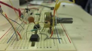
How to Connect a Potentiometer on a PCB
Connecting potentiometers on the PCB needs careful planning and correct steps. A small pot wiring mistake can cause unstable signals, noise, or wrong voltage levels. In addition, incorrect orientation or pin connection may damage the circuit. Therefore, you must follow a clear step-by-step process to ensure reliable potentiometer wiring.
Step #1: Understand the Potentiometer Pins
Most potentiometers have three pins. There are two outer pins across the resistive track element, and one wiper that moves along it. Knowing the pins’ functions helps you avoid incorrect connections and gives you proper control.
Step #2: Decide How You Will Use the Potentiometer
- As a Voltage Divider: Connecting Pin 1 with VCC and Pin 3 with ground gives you a variable-voltage output.
- As a Variable Resistor: Connect pin 2 with pin 1 or pin 3. It gives a variable resistance without changing the voltage.
Step #3: Choose the Correct Potentiometer
Selecting the right potentiometer is crucial. In this case, always check the resistance and power rating first. Then, choose one that fulfills your electrical needs and supports your design. Lastly, make sure the mounting type matches your design.
Step #4: Place the Potentiometer Footprint on the PCB
Download or create your own footprints according to your specific pot. The hole spaces and pad sizes must be accurate. Maintain a proper gap between components so the knob does not hit other parts while moving.
Step #5: Connect the PCB Traces
Route the traces carefully from the pad to the circuits. If the current is high, use wider traces for power pins. To achieve a stable voltage output from the wiper, keep signal traces short to reduce interference.
Step #6: Add Protection and Filtering
To filter out electrical noises, you can add a small capacitor between the wiper and ground. It creates a debounce effect. Similarly, add a series resistor to prevent a short circuit when the pot is at zero.
Step #7: Check the Orientation Before Soldering
Before soldering, check the pot face to see if it is the right way. Wrong orientation may reverse the outcome. So, double-check the pins’ order and rotation directions. A quick review might save time and money on rework.
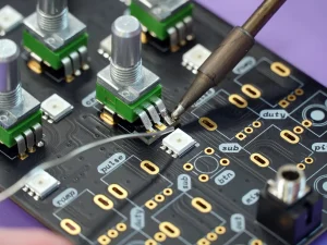
Step #8: Solder the Potentiometer on the PCB
How to connect potentiometer? Firmly insert the potentiometer into the PCB. Make sure each pin is soldered perfectly. In this step, avoid using excess solder and cold joints. Ensure the components sit flat. This way, proper soldering ensures better electrical connections and long-term strength.
Step #9: Test the Potentiometer on the PCB
After soldering, check the potentiometer using a multimeter. Rotate or slide the wiper slowly. Verify the voltage changes. Here, the smooth variation confirms correct wiring. Thus, testing lets you know the pot connection is working as smoothly as expected.
Frequently Asked Questions
What is the difference between 50k and 100k potentiometers?
The main difference is the resistance value. A 100K potentiometer offers higher resistance than a 50 K potentiometer. Higher resistance reduces current flow. Also, it increases electrical noise in the circuit. So, a circuit responds differently based on the resistance.
Can I use a 100k potentiometer instead of a 10k?
Yes, you can, but it may cause issues. The 100K pot significantly changes the current flow in a circuit. Especially in Arduino, a 100K pot might result in unstable readings. The best option is to stay as close as possible to the original value.
Can a Potentiometer be used in a humid environment?
Typically, standard potentiometers fail in humid conditions. Humidity causes rust in the track. So, you may use sealed or IP-rated potentiometers for damp areas.
How does a potentiometer affect the automation system?
A potentiometer provides vital control to the automation. It works by converting mechanical movement into electrical signals. As a result, it controls speed, position, and setpoints. However, poor quality or noisy pots may sometimes cause unstable signals.
Final Thought
Correct potentiometer wiring is just as important as selecting the right type. Even a high-quality component can fail if the pot wiring is wrong. Poor wiring may cause noise, unstable control, or long-term PCB damage.
In complex circuits, a minor mistake can lead to costly rework or product performance. A well-designed PCB also supports accurate potentiometer pin configuration and reliable soldering.
For the best results, choose a trusted PCB manufacturer. UETPCB delivers high-quality PCBs that support precise pot wiring and long-term circuit reliability. Contact us if you plan to produce PCB with potentiometers in mass. For all types of PCB projects, UETPCB could be your trusted partner.