
The world of electronics literally depends on direct current (DC). Alternating currents are unsafe for most sensitive electronic devices. However, if not using batteries, the alternating current is first converted to direct current. Which then becomes suitable for use in the device. But not all devices use the same level of dc voltage. Each device, even each component on the PCB, needs a different voltage level. To better understand how these devices work, the use of the DC voltage symbol is critical.
You can think of electric cars, solar panels, and some portable equipment that require higher voltages. On the other hand, Sensors, watches, and pacemakers require low-voltage levels.
All modern devices are powered by complex PCBs. If you observe it, you will find that it consists of various components, such as capacitors, resistors, and ICs. In reality, each of these components cannot operate at the same voltage. Instead, they use different voltage levels controlled by various resistors.
This article explores how the DC voltage symbol is used on PCBs and multimeters. You will get familiar with some common types of DC volt signs. You will also learn how AC voltage and DC voltage differ.
Understanding DC Voltage and DC Power on PCB?
PCBs, or printed circuit boards, run on direct current. It is primarily green (some are red or blue) inside most electronic devices. Its main job is to connect all the components and ensure the whole device functions properly.
DC, or direct current, only flows in one direction. It does not change back and forth. Unlike alternating current, direct current doesn’t change polarity. Thus, it is ideal and considered safe for electronic devices.
As mentioned before, different parts of the PCB may require different voltage levels. For example, in a complex circuit, a processor may require a lower voltage, while a motor driver may require a higher one. So, how do you know which component needs which voltage level? These differences must be clearly shown, and this is done through symbols. The DC voltage symbol shows where power comes from and where it goes. It typically makes the circuit easier to read.
You may also see the DC volts symbol next to numbers like 5V or 12V. It tells you the exact voltage. Moreover, the DC voltage sign also shows polarity. It tells you which side is positive and which is negative. If polarity is wrong, parts can break.

Applications of DC Voltage
DC voltage is one of the most widely used supply voltages in everyday applications. Its widespread use ranges from mobiles and laptops to small controllers and sensors.
Nowadays, modern EV’s run on DC power. Even oil-based or gas-based vehicles require a battery to start the engine. Its dashboards and controllers also rely on DC power.
Solar panels produce DC voltage from sunlight. Batteries store energy as DC voltage and supply it when needed. Medical devices, such as pacemakers and heart monitors, also rely on DC power.

What is the Symbol for DC Voltage?
The DC voltage symbol is internationally recognized. However, it may appear in different forms. The type of the DC voltage symbol depends on where you are using it.
The most common DC voltage symbol is a straight line over a dashed line. This symbol is based on international standards for DC power devices. It is often used on power supplies and electronic devices.
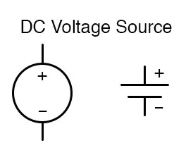
In circuit diagrams, a battery symbol is a very common sign for dc voltage. Sometimes it uses plus-minus signs, and sometimes it just uses two parallel lines. Here, the longer line is positive, while the shorter one is negative.
A DC source can also be shown as a circle with plus and minus signs. On measuring devices, the DC voltage symbol is shown near the V mark.
Standard DC Voltage Symbols Used in Schematics
Throughout various electronic devices, you may find four significant types of DC voltage symbols. They do not represent the same type of information. Instead, some symbols represent a voltage source. In contrast, some indicate the polarity or reference points.
For example, if you consider a battery source, you will find that it doesn’t work the same way as a regulated DC supply. Also, ground symbols do not show the power source.
Basic DC Voltage Symbol
Among the four signs, the straight line with a dashed line is the most common. It follows the V sign and mainly denotes the DC voltage. The solid line on the symbol represents the positive side. On the other hand, the dashed line represents the negative or ground side.
You can find these symbols for DC volts on low-voltage devices. It is also used in simple circuit layouts and many power supply schematics.
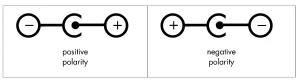
Polarity Symbols (+/-)
Polarity sign is the next most common type of dc voltage symbol. It is widely used on ICs, diodes, and LEDs.
The plus sign (+) on the polarity sign denotes the positive terminal, and a minus sign (-) shows the negative terminal. With this sign, you can understand in which direction the electricity flows. If you accidentally reverse it, it can break parts in LEDs or ICs.
Battery and DC Source Symbols
A battery sign has two parallel lines of different lengths. The longer side represents the positive terminal. On the other hand, the shorter line represents the negative terminal. The symbol also talks about series cells, however, as circles with a sign.
People often use this kind of DC voltage symbol in circuits powered by batteries. Many portable gadgets and schematic diagrams also use it.
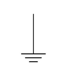
Ground and Reference Symbols
Ground symbols don’t show the volts; they show where the circuit is grounded. The sign features a vertical line
and three horizontal lines. In fact, ground symbols also have different kinds. The most commonly used signs are chassis ground, earth ground, and single ground. This kind of DC voltage symbol is often used in PCB layouts and test settings.
DC Voltage Labels and Net Names on Schematics
Labels are short, brief texts that indicate exact power levels, like +5V and +12V. On the other hand, a net name is the node where multiple wires connect, and all have the same potential. For example, all wires at 5V are called VCC or +5V.
On schematics, you will generally need both DC voltage labels and net names. They both help to identify different circuit parts.
Net names and labels are both essential for testing. You will be able to find out the exact node voltages with the help of these symbols. It also minimizes flaws and makes the circuit safer to use.
Multimeter DC Voltage Representation
A digital multimeter is a safe and easy way to measure DC voltage. On most digital multimeters, the AC and DC voltage sections are separate. Usually, the DC voltage section is on the left. It is labeled with V with a straight line and a dashed line. Here, you can see numbers starting from 200m to 1000. 200m represents 200mV, and 1000 is for the 1000V.
When checking the DC voltage, set the dial to the DC voltage setting. In this case, always set the voltage to the equipment’s nearest voltage level. For example, you are about to measure a nearest 12V battery or circuit. On the digital multimeter, select 20V as the reference voltage. If you chose 200, you can not get the actual data. Or, if you choose 2000m or 2V as the reference line, you will see ‘OL’ or ‘over limit’.
You must also be careful with the probe’s positioning. Usually, a digital multimeter has two probes. One is black, and the other one is red. Note that the black probe must be connected to the COM Port and the red one to the “V” port. Some digital multimeters have three ports: one for COM and two for AC and DC. If you have these devices, you must insert the correct probe into the proper port before measuring.
DC Voltage Vs AC Voltage
Both AC and DC are widely used in our everyday lives. We use AC at home to run fridges, stoves, AC, lights, and machinery. We also use AC to run many DC-powered electronics. However, the AC is first converted to DC. For instance, a mobile charger, a computer CPU, a monitor, TVs, and so on.
The following table shows the differences between DC voltage and AC voltage.
| Feature | DC Voltage | AC Voltage |
| Flow Direction | One direction only | Alternates direction continuously |
| Source | Batteries, solar panels, DC adapters | Mains electricity, generators |
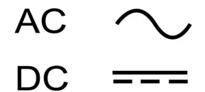
| Symbol | Straight line or “V⎓.” | Wavy line (~) |
| Voltage Level | Constant or steady | Varies periodically |
| Storage | Can be stored in batteries | Cannot be easily stored |
| Application | Electronics, sensors, motors | Home appliances, industrial machines |
| Measurement | Multimeter with DC setting | Multimeter with AC setting |
Summary
DC voltage is a continuous flow of electricity in one direction. These symbols help us identify it on schematics and PCBs. It shows the accurate voltage level, such as 5V or 12V. Also, the emblem shows polarity, so you can tell which terminal is positive and which is negative.
Consequently, this practice prevents mistakes and makes the circuit easy to study. You can use tools like multimeters to measure voltages accurately. Once you understand the symbols, you can choose the right component for the PCBs.
If you have any questions, feel free to reach out to our customer support team. We have a friendly team always ready to assist you.