There are some important steps you can take to check for short circuits in your PCB:
Step 1: How to find a short circuit board in PCB?
Step 2: How to Check Short Circuit board in PCB?
Step 3: How to find faulty components on a PCB?
Step 4: How to test the PCB destructively?
Step 1: How to find a pcb short circuit?
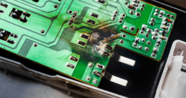
Visual Inspection
The first step is to examine the entire surface of the pcb short circuit. If so, use a magnifying glass or low-power microscope. Cracks or spots in any solder should be noted. Check all through holes. If none-plated through holes are specified, make sure this is the case on the board. Poor plating through holes can cause a pcb short circuit between layers and cause everything you have to ground, VCC or both together.
If the pcb short circuit is really serious and causes the component to reach a critical temperature. You will actually see burn spots on the printed circuit board. They may be small, but they will turn brown instead of the normal green solder.
If you have multiple boards, a burned PCB can help you narrow down the area in a particular location without having to power another board, sacrificing the search area. Unfortunately, there were no burns on the circuit board itself, just unlucky fingers checking to see if the IC was overheating.
Some pcb short circuits will occur inside the circuit board and will not produce a burn spot. This also means that they will not be noticed from the surface. Here, you will need other methods to detect short circuits board.

Infrared Imaging
Using an infrared thermograph can help you locate areas that generate a lot of heat. If an active component is not seen away from a hot spot, a PCB short circuit may occur even if the short circuit occurs between the inner layers.
Pcb Short circuits usually have a higher resistance than normal wiring or solder pads because they have no benefit of optimization in the design (unless you really want to ignore rule checking).This resistance, along with the naturally high current generated by the direct connection between the power supply and the ground, means that the conductor in the short circuit of the PCB will heat up. Start with the lowest current you can use. Ideally, you would see a pcb short circuit and then cause more damage.
Step 2: How to test the short circuit in PCB board?
In addition to the first step of checking a circuit board with a trusted eye, there are several other ways you can find the potential cause of a PCB short circuit.
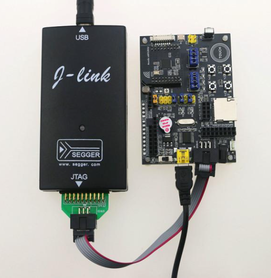
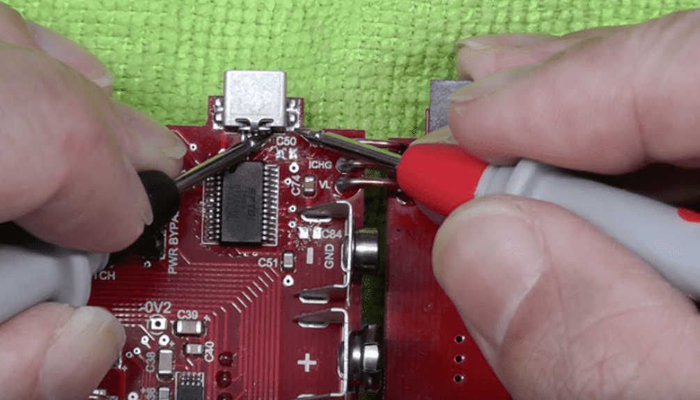
Test pcb short circuit with a digital multimeter
To test the circuit board is a short circuit board or not. You need to check the resistors between the different pads in the circuit. If the visual inspection does not reveal any clues as to the location or cause of the short circuit board, grab the multimeter and try to trace the physical location on the pcb short circuit. The multimeter approach has received mixed reviews in most electronic forums. But tracking test points can help you figure out what the problem is.
You will need a very good multimeter with good sensitivity, which is easiest if it has a buzzer function to alert you when pcb short circuits are detected. For example, if the resistors between adjacent wires or pads on a PCB are measured, high resistors should be measured.
If the resistor between the two conductors to be measured in a separate circuit is very low, the two conductors may be bridged either internally or externally. Note that bridging two adjacent wires or pads with an inductor (for example, in an impedance matching network or discrete filter circuit) will result in very low resistance readings because the inductor is just a coil conductor. However, if the two conductors on the board are far apart and the resistance you read is small, there will be a bridge somewhere on the board

Tests short circuit board relative to the ground
Particularly important is short circuits involving ground through-holes or connecting formations. A multilayer PCB with an internal layer will include a return path through the assembly near the through-hole, which provides a convenient location for checking all other through-holes and pads on the board surface layer. Place one probe on the ground connection and touch the other probe on the other conductors.
The same ground connection will also exist at other locations on the board, meaning that if each probe is touched to two different grounding through-holes, the reading will be small. Pay attention to the layout when doing this, because you don’t want to mistake a pcb short circuit for a common ground connection. All other ungrounded bare conductors shall have a high resistance between the common ground connection and the conductor itself. If the value read is low and there is no inductor between the conductor in question and the ground, the component may be damaged or pcb short circuited.
Pcb short circuit components
Checking for pcb short circuits in components also involves measuring resistors using a multimeter. If a visual inspection does not reveal excess solder or sheet metal between the pads, a pcb short circuit may be formed in the inner layer between the pads/pins on the assembly. A short circuit may occur between the pads/pins on the assembly due to poor soldering. This is one of the reasons PCB should undergo DFM and design rule checks. Close soldering and perforations may short-circuit accidentally during manufacturing.
Here, you need to measure the resistance between the pins on the IC or connector. Adjacent pins are particularly easy to pcb short circuits, but these are not the only places where short circuits can occur. Check that the resistance between the pads/pins are relative to each other and that the ground connection has low resistance.

Narrow location
If you think there is a short circuit between two conductors or between one conductor and the ground, you can narrow the position by checking nearby conductors. Connect one wire of the multimeter to a suspiciously pcb short circuit connection, move another wire to a nearby different ground connection, and check the resistance. As you move further to the ground, you should see a change in resistance. If the resistance is increased, you are removing the grounding wire from the pcb short circuit position. This helps you narrow down the exact location of the short circuit, even to a specific pair of pads/pins on the component.
Step 3: How to find faulty components on a PCB?
A faulty component or improperly installed component can be part of a pcb short circuit that causes many problems on the circuit board. Your components may be defective or forged, causing a short circuit or short-circuit phenomenon.
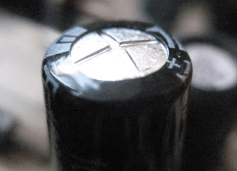
Adverse element
Some components deteriorate, such as electrolytic capacitors. If you have suspect components, check those components first. If you’re not sure, you can often do a quick Google search for components that you suspect are “failing” to find out if this is a common problem. If you measure a very low resistance between the two pads/pins (neither of which are ground or power pins), a burnt component may cause a pcb short circuit. This is a clear indication that the capacitor is broken. The capacitor also bulges if it goes bad or if the voltage applied exceeds the breakdown threshold.
Step 4: How to test the PCB destructively?
Destructive testing is obviously a last resort. If you can use an X-ray imaging device, you can examine the inside of the circuit board without breaking it.
In the absence of X-ray devices, you can begin to remove components and run the multimeter tests again. This helps in two ways. First, it gives you easier access to pads (including thermal pads) that may short-circuit. Second, it eliminates the possibility of short-circuiting the faulty component, allowing you to focus on the conductor. If you try to narrow down the short circuit to the connection on the component, such as between two pads, it may not be clear whether the component is defective or if there is a short circuit inside the circuit board. At this point, you may need to remove the component and check the solder pad on the board. Unmounting the component allows you to test whether the component itself is defective or whether the solder pad on the board is bridged internally.
If the location of the short circuit board(or possibly multiple short circuits) remains elusive, you can cut through the circuit board and try to narrow the pcb short circuit. If you are familiar with the general location of the short circuit, you can cut a section of the circuit board and repeat the multimeter test on that section. At this point, you can repeat the above tests with a multimeter to check for pcb short circuits at a particular location. If you’ve reached this point, your shorts have been particularly elusive. This will at least allow you to narrow the short circuit board to a specific area of the circuit board.
