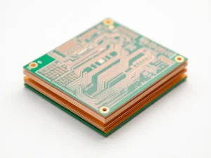
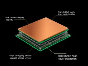
Regarding PCBs, circuit board copper thickness becomes a critical topic. This thickness depends on several factors. However, the amount of current needed to carry is the most vital. This article mainly gives you an idea of the typical PCB copper thicknesses.
Standard Circuit board copper thickness
Copper thickness may vary depending on current capacity and temperature. However, some standard values are widely used in PCB production. This standard PCB copper thickness makes production and replacement easier. Copper thickness is typically measured in ounces per square foot or mils. In general, you will find four standard PCB copper thicknesses.

- 5 oz/sq ft: This standard size has a copper thickness of 0.6 mils or 17.05 microns. It is used in low-power devices or simple circuits.
- 1 oz/sq ft: This standard size has a circuit board copper thickness of 1.34 mils or 34.1 microns. Most general-purpose electronic devices have this copper thickness.
- 2 oz/sq ft: This standard size has a PCB copper thickness of 2.68 mils or 68.1 microns. This type of PCB copper thickness is used in power supplies, motor controllers, and power circuits.
- 3oz/sq ft: This standard size has a circuit board copper thickness of 4.02 mils or 102.2 microns. Heavy-duty vehicles, power circuits, and industrial machines need this thickness.
Circuit board copper thickness Depends on the Current Flow
Copper thickness mainly depends on the amount of current it will carry. Indeed, the more current, the greater the circuit board’s copper thickness. Finding the right copper thickness for the circuit board is crucial to keep it from getting too hot.
A PCB can usually carry more electricity when its copper is thicker. Also, it can efficiently dissipate heat. Therefore, you must choose the right copper thickness for the circuit board to ensure a better service life. In this case, one of the most common ways to find this is by using the empirical formula and IPC standard. IPC-2221 standards are generally used to determine the thickness of PCB copper.
You may already know the formula: W = k x (Tr)^0.44 x I. In this case, W stands for the copper trace’s width. This number, k, stays the same no matter what the PCB is doing. Tr is the temperature rise, and “I” is the current. This way, you can find the correct copper trace width. Table IPC-2152 can also help you find the PCB trace width for your project. This table shows the rise in temperature, the amount of current that is wanted, and the weight of the copper.
What is the thickness tolerance of copper in PCB?
Every tolerance value generally has an upper and lower bound. This bound tells you what thicknesses are allowed when you design a PCB. In general, the tolerance for copper thickness is ±0.15mm. You need tolerance of copper thickness to ensure that the current flows effectively through it. Also, it plays a crucial role in dissipating the heat.
What is the maximum thickness of copper in PCB?
The maximum circuit board copper thickness is usually around 2.8mm. However, you may also choose thicker copper layers. Generally, you can reach up to 3mm in the outer and 1 mm in the inner layers.
Contact Us Today!
If you have any questions, don’t hesitate to contact our customer service team at UETPCB. We offer a full range of PCB fabrication services. We handle our facility’s manufacturing and assembly process, including sketches and drawings. You can learn more about our services on our services page.

