Reading circuits is tricky if you don’t know how to read. The messy connections are sometimes complicated to sort out. In this case, electrical and electronic symbols play a crucial role. These symbols typically make the circuit design easy to understand. And it is generally divided into two main categories: electrical symbols and electronic symbols.
Using the correct symbols can save a lot of time. This way, you can quickly identify components. It also helps avoid mistakes when building or troubleshooting a circuit.
This article typically highlights all commonly used electrical and electronic symbols in circuits. Although hundreds of symbols are used, we have attempted to mention the most widely used ones.
You might also find the same component with different symbols. This occurs due to the various standards used in different countries. Additionally, numerous custom components are used on the circuit, resulting in a unique electronic symbol.
Introducing Electrical and Electronic Symbols
Electrical and electronic symbols are usually used to demonstrate the circuit. It’s a universal language of designing circuits. As we use letters to form words, it’s a similar concept that makes it easier for us to understand circuits.
Additionally, it enables engineers, technicians, and students to read and understand circuit diagrams. If you know these symbols, you will be able to visualize how a circuit works without physically building it.
One of the best advantages is clarity. Imagine using ordinary language to describe the circuit without using symbols. Wouldn’t it be pathetic? This may lead to errors and confusion. On the other hand, each symbol indicates its nature and properties. Overall, they have unique shapes and meanings of usage.
Sometimes, symbols may vary with the nation or international standards. There are numerous standards for these symbols worldwide. Examples of these standards include ANSI, IEEE, IEC, and JIS, among many others. Here, the designs may differ slightly. But the primary purpose is the same for both systems.
For electrical and electronic engineers, as well as beginners, this is a crucial topic to learn. They prepare students for circuit analysis, PCB design, and troubleshooting. Later, it will help you in your professional life. It’s the first step towards making and mastering electronic devices.
Why Do We Use These Symbols?
As you are aware, people use electrical symbols in circuits to gain a clear understanding of the concepts. Similarly, they use electronic symbols for the same reason. Why should we use electrical and electronic symbols? Well, it helps us to know how electricity flows in the circuit. Additionally, it helps us avoid making mistakes in the application field.
Universal Language
Electrical and electronic symbols create a universal language in engineering. You may understand where you belong on the earth. It removes the language barriers in technical sectors.
- Common across countries
- Removes language barriers
- Supports global collaboration
Saves Time
With symbols, circuit descriptions are shortened to quick visuals. Instead of long sentences, engineers use these short electrical and electronic symbols. This speeds up the design and analysis of the circuits.
- A quick description
- Easy to understand
- Quick process for design
Increase Accuracy
Using standard symbols means a lower chance of making errors. They remove guesswork. To increase safety and reliability, here accuracy matters a lot.
- Reduce mistakes
- Improve performance
Simplifies Complexity
When you use these symbols in complex circuits, it will be easier for you to understand. This makes diagrams neat and clean so they can be used for work, school, and training.
- Clean layout
- Easy interpretation
Supports Learning
Symbols are simple enough for newbies to grasp. They replace complicated descriptions with simple icons. Mostly, this helps the students and trainees build a strong foundation.
- Helps beginners
- Easy memorization
- Solid groundwork
Electrical and Electronic Symbols Chart
There are numerous types of electrical and electronic symbols used in circuit diagrams. However, the following symbols in the chart are the most commonly used. These symbols are typically enough to understand all general-purpose electrical and electronic circuits.
 |
 |
 |
 |
 |
 |
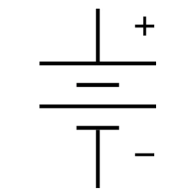
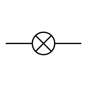
| Switch (Open) | Switch (Close) | Cell | Battery | Lamp | Fuse |
 |
 |
 |
 |
 |
 |
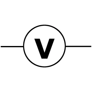
| Voltmeter | Ammeter | Motor | Buzzer | Ground | Transformer |
 |
 |
 |
 |
 |
 |
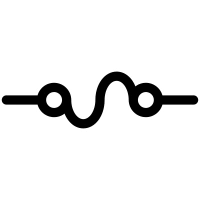
| Resistor | Capacitor | Diode | Zener Diode | Photodiode | LDR |
 |
 |
 |
 |
||
| Thermistor | Transistors | IC | Relay | Crys Oscillator |
Electrical Symbol
An electrical symbol typically represents the basic electrical components. It could be used to carry, measure, or control electric current in a circuit. You may find these components in power circuits or high-current devices.
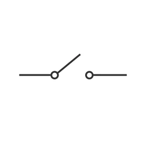
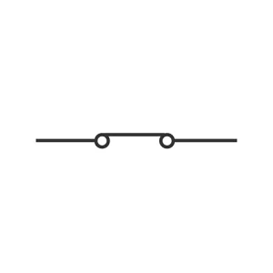
Switch (Open & Close)
A switch typically opens and closes a circuit. It controls the flow of electricity. When closed, current flows, and when open, the current stops.
There are various types of switches used in circuitry. Some common types are toggle, push-button, slide, rotary switches, and many more. Switches are everywhere. Starting from lights, motors, alarms, to large industrial machinery, they all need switches.
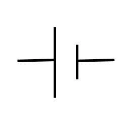
Cell
A cell is a unit of an electrical source. It converts chemical energy into electrical energy, which then flows as an electric current in a circuit.
These cells can be rechargeable or non-rechargeable. They are used in remotes, torches, or in simple DC circuits as the power source.
Battery
A battery is a group of cells connected in series or parallel. Typically, it provides higher voltage and currents in the circuit.
There are many types of batteries, including dry cell batteries, lithium-ion batteries, lead-acid batteries, and others. They are being used in cars, by UPS, in laptops, mobile phones, and for renewable energy storage.
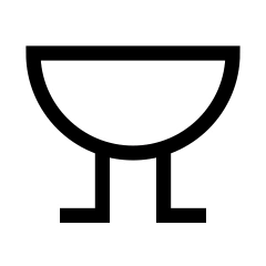
Lamp
Lamps are an electrical device that converts electrical energy into light. It uses a filament or LED to glow when current passes through it.
Types of these lamps include incandescent, fluorescent, and LED lamps. They are used in lighting circuits, indicators, and testing circuits.
Fuse
A fuse is a protective device that melts when the current flow reaches the safety limit. In this process, it disconnects the circuit to prevent damage or health risks.
Cartridge fuses, resettable fuses, and glass fuses are some of the common types. For safety purposes, it is used in home wiring, electronic devices, and automotive circuits.
Voltmeter
A voltmeter is typically a measuring device that measures voltage across circuit elements. To measure the voltage, the voltmeter is connected in parallel with the component.
Types of voltmeters include analog and digital meters. Primarily, people use it for electronic testing, power supply measurement, or in laboratories.
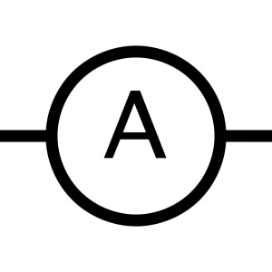
Ammeter
An ammeter is a current-measuring instrument that connects in series with an element. When current flows, it indicates the measurement.
Types of these ammeters are moving coil, moving iron, and digital ammeters. People use ammeters for motor testing and troubleshooting in circuits. It can also be used for battery charging.
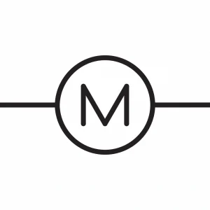
Motor
Motors usually convert electrical energy into mechanical energy. It spins when current flows through its windings, creating a magnetic field.
DC motors, induction motors, and synchronous motors are some of the types. It finds applications in fans, pumps, machines, and vehicles. You can also use it in household appliances.
Buzzer
The buzzer is an electrical device that produces an audible sound. When electricity passes through it, typically via a vibrating diaphragm, it makes a signal or tone.
Piezoelectric and electromagnetic buzzers are examples of their types. These buzzers serve as alarms, indicators, toys, or other devices.
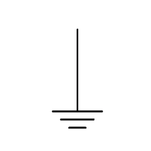
Ground
Ground is a fundamental part of a circuit. It indicates the reference point in a circuit. This means it connects to the earth, which has a voltage of 0. This way, it provides a path for excess current to flow safely.
There are many types of grounding. Some of the common grounds are earth ground, chassis ground, and signal ground. Ground is essential for electrical wiring, circuits, and safety systems.
![]()
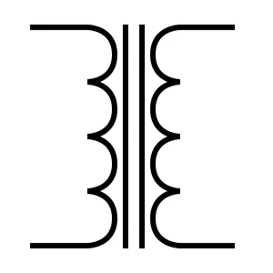
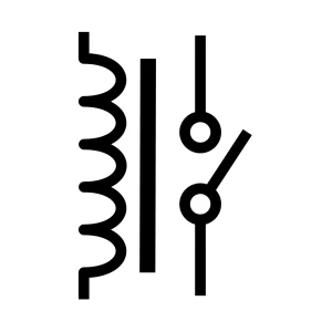
Transformer
Using electromagnetic induction, a transformer moves electricity from one channel to another. It steps up or steps down the voltage without changing frequency.
Types of these transformers are step-up, step-down, isolation, and autotransformers. All of these transformers are used in power distribution, chargers, inverters, and various electronic devices.
Electronic Symbol
An electronic symbol, on the other hand, represents a component used in electronic circuits. These components typically control or manipulate electrical signals. They are widely used in low-voltage circuits. Common examples include signal processing, logic, or amplification.
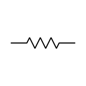
Resistor
The resistor is an electronic component. In general, a resistor limits the current in a circuit. It converts electrical energy into heat, controlling the flow of voltage and current. They are the reason for voltage drops in circuits.
Fixed, variable, light-dependent, and thermistors are common types of resistors. Utilize in circuits for protection, filtering, amplification, and power supply applications.
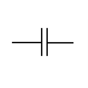
Capacitor
Capacitors conserve electrical energy using charges. Then, it converts the energy in the electric field between two plates. They can help to lower voltage pulses.
Ceramic, electronic, mica, and other types of capacitors are available. People use them in fans, filters, timing circuits, and many other devices.
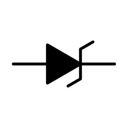
Diode
A diode is a two-terminal electronic component. It is made of semiconductor materials that work as a one-way switch. This means it can only pass electricity in one direction.
Common types include PN junction diodes, also known as basic rectifiers, and zener diodes. Apart from them, there are photodiodes or LEDs. Typically used in the demodulation of signals and safety systems.
Zener Diode
A Zener diode is a type of PN junction diode used to allow current to flow either forward or backward. It regulates voltage.
For general use, standard Zener diodes can be used. For compact devices, use surface-mount Zener diodes for better outcomes. Besides, you may use temperature-compensated or precision Zener diodes.
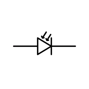
Photodiode
Photon diodes have arrow symbols to indicate them. It converts light energy to electrical energy by generating holes. These are electron holes paired when light strikes the PN junction.
Photon diode types are PIN, APD, Schottky Photodiode, and others. The majority of people use them in optical systems, automation, medical devices, and so on.
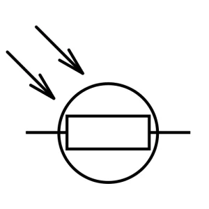
LDR
LDR, also known as a Light-Dependent Resistor, changes its resistance in response to light. When the intensity of light increases, the resistance increases too. Contrast happens when the intensity is lower.
Primarily, there are two types of LDR: intrinsic LDR and the other is extrinsic LDR. Both serve in automatic lights, solar devices, and brightness control circuits.
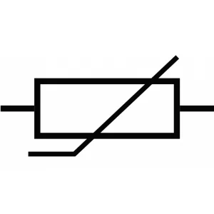
Thermistor
A thermistor is typically a resistor. It alters the resistance in relation to heat. For this reason, it is often referred to as a temperature-sensitive resistor.
The two main types of thermistors are NTC (negative temperature coefficient) and PTC (positive temperature coefficient). They are used in temperature sensors, motor protection, and fire alarms.
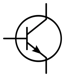
Transistors
A transistor is a semiconductor device that can amplify or switch signals. It controls current flow using a small input signal. Transistors can control both large and small amounts of current.
Transistor types are NPN, PNP, MOSFET, and others. Manufacturers use them in amplifiers, switches, microprocessors, and digital logic circuits.
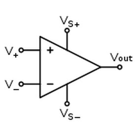
IC
An IC (Integrated Circuit) or microchip is a small electrical circuit with many parts. It performs complex functions.
ICs can be categorized in several ways. Examples of these categories include analog ICs, digital ICs, and mixed-signal ICs. Used in computers, smartphones, and control systems.
Relay
A relay is an electromagnetic switch. A small current controls a larger current circuit. It allows us to open or close circuits without any mechanical contact.
Relay types are electromechanical, solid-state, and latching relays, among others. You can use it in automation, safety systems, and motor controls.
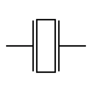
Crys Oscillator
A crystal oscillator is a type of electronic circuit that generates stable and accurate signals. This one utilizes mechanical resonance, typically achieved with quartz. To begin, it turns electrical energy into vibrations. In this way, it creates back-to signals at a certain frequency.
There are various types of oscillators, like CCO, VCXO, and TCXO, used in clocks and computers.
Summary
Electrical and electronic symbols typically make circuit diagrams easy to read and understand. They clearly and precisely show each component. In this case, we can sort them into two groups: electrical symbols and electronic symbols.
Electrical symbols typically deal with ASIC power and control devices. On the other hand, we use electronic symbols mainly for signal processing. They are both essential and used in a wide range of applications.
The electrical circuit symbols chart typically highlights all the most commonly used symbols in circuit design. If you have found new types of symbols, feel free to contact us. We can help you understand your circuit.