Analog devices often need messy setups. It not only increases the maintenance needs but also can not offer long-term durability. Sensor setups are no exception. The analog setup for sensing devices often needs multiple wires, extra boards, and complicated connections. A sensor PCB solves this problem by combining sensors directly onto a compact PCB.
The design of the sensor PCB makes the whole system neat, reliable, and highly efficient. It could be temperature, pressure, IR, light, radiation, or motion sensors. The touch of digitalization allows us to get accurate readings as well as efficient setups.
This article mainly talks about sensor PCBs, their types, benefits, and applications. It also highlights the step-by-step process of the sensor PCB design guide.
Overview of Sensor PCB
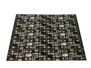
A sensor PCB comes with a printed circuit board with the necessary components on it. It can integrate different types of sensors into one compact unit. The PCB connects the sensors with circuits or traces. These tiny connections make the system easy to use and reliable.
Instead of using many wires and separate boards, the sensors are built directly on the PCB. This setup typically allows smooth data collection and fast communication with other devices. The best part is that the sensor PCB is very flexible. You can customize it based on your project needs.
Sensor PCBs are widely used in many applications. The smartphone you are using, medical devices, smart home products, industrial machines, and even in your car, have their uses. Based on different sensing needs, you can use a specific type of PCB sensors. Compared to traditional sensor devices, sensor PCB offers several pros and cons.
Pros
- Sensor PCB comes with a compact design. Compared to analog sensors, it is much lighter and easier to carry.
- The sensor PCB doesn’t need wiring to connect sensor components. Instead, it uses pins, pads, and traces to complete connections.
- Analog sensors may have bigger tolerances, while the sensor PCB is much accurate and reliable.
- It is easy to install and portable.
- Sensor PCBs are cost-effective.
- You can install multiple sensors on a single board.
Cons
- The manufacturing process of making PCB sensors is quite complex. The initial cost of the production line is very expensive. However, the per-part PCB sensor cost is much cheaper than a regular sensor PCB.
- The sensor PCB design needs skilled engineers.
- Once damaged or malfunctions, it is difficult to repair. You might have to think about changing the sensor device.
Types of Sensors for Sensor PCB
Sensing devices may have various types. When in motion, you need a way to measure the speed, velocity, and acceleration. When in space, you need something to detect gravity. In industries, you need something to detect temperature and humidity. Like this, there are hundreds and thousands of situations where you may need a specific type of sensor. Let’s check some of the most popular types of sensors for the sensor PCB.
Environmental Sensors
Environmental sensors typically measure and monitor conditions around us. They often include temperature, humidity, pressure, light, and so on. With a sensor PCB, these sensors become compact, accurate, and reliable.
| Sensor Name | Functions | Applications |
| Temperature Sensor: | It measures heat and cold levels. | HVAC, medical devices, electronics |
| Humidity Sensor: | It detects moisture levels in the air. | Weather stations, greenhouses, storage |
| Pressure Sensor: | It monitors air or liquid pressure. | Automotive, medical equipment, and pumps |
| Light Sensor: | It measures light intensity. | Smart lighting, cameras, displays |
| Radiation Sensor: | It detects harmful radiation levels. | Nuclear plants, healthcare, labs |
| Gas Sensor: | It identifies gases like CO2, CO, methane, and other gases. | Safety systems, factories, homes |
Motion and Position Sensors
When in motion, you must pay attention to vibration and noise. In such situations, analog devices often get high tolerance readings. Sensor PCBs revolutionized many industries. Because of this, we have many modern devices that make our lives easier and faster.
Motion and position sensors typically track movement, direction, and speed. They help machines and devices to understand how objects or people move in space. When you add the sensors to a PCB, they deliver fast and precise feedback for automation, safety, and smart electronics.
| Sensor Name | Functions | Applications |
| Accelerometer: | It detects acceleration and tilt. | Smartphones, wearables, robotics |
| Gyroscope: | It measures rotation and angular velocity. | Drones, gaming devices, navigation |
| Motion Sensor: | It identifies motion in an area. | Security systems, lighting control |
| Proximity Sensor: | It detects objects nearby without contact. | Cars, smartphones, automation systems |
| Position Sensor: | It tracks the exact position of an object. | Robotics, industrial machines, and medical tools |
Biometric and Human Interface Sensors
Biometric and human interface sensors typically read data from the human body. It could be retina, fingerprints, face detections, or voices. With the integration of these sensors, we can create smart devices for more security. The best examples are smart modern devices we use recently, including smartphones and laptops.
| Sensor Name | Functions | Applications |
| Biometric Sensor: | It reads fingerprints, face, or iris patterns. | Smartphones, security systems, and banking |
| Sound Sensor: | It detects and measures sound or voice. | Voice assistants, audio devices, and alarms |
| Image Sensor: | It captures images and light data. | Cameras, medical imaging, and drones |
Force and Magnetic Sensors
This type of PCB sensor detects strength and magnetic fields. These sensors on a PCB are vital in automation, robotics, navigation, and advanced machines. They ensure precision and efficiency in many modern technologies.
| Sensor Name | Functions | Applications |
| Force Sensor: | It measures push, pull, or weight. | Robotics, weighing machines, and medical devices |
| Magnetic Sensor: | It detects magnetic fields and metal objects. | Navigation, smartphones, automotive |
Sensor PCB Design Guide
Maybe you are planning to create your first sensor PCB. The good news is that UEPTCB offers you a complete package for making various types of sensor PCB. From design to delivery, you can communicate with their technical team to complete the project. We follow a step-by-step process to create each sensor PCB to the highest quality standards.
Step #1: Define Requirements
AT UETPCB, we first begin by defining the requirements. We take project requirements, like layout counts, Gerber files (if have), materials, conformal coating, and so on. Depending on what we have collected, we have an internal discussion to develop the best solution. Finally, we prepare a list of EQ and discuss with you to finalize the production plan.
Step #2: Choose the Right Type of Sensor
When answering the Engineering Questions, you must pay attention to choosing the right type of sensor. There are many different types of PCB sensors. Even a single temperature sensor has lots of varieties. In this case, you must consider the size, cost, and mounting features. Even if your chosen sensor is difficult to manage, we can suggest some alternatives.
Step #3: Schematic Design
Once all the engineering questions are answered, we begin creating the first schematic design. This step may not be necessary if you already have the design in your hand. Depending on the suggestions, we can suggest some critical adjustments. However, if you do it, make sure the connections are correct and the signals are clear.
Step #4: PCB Layout
Next, we convert our schematic design into different PCB layers. In this step, maintaining the thickness is critical work. We typically hold a thickness tolerance of ±0.05 to ±0.1mm. Here, the component placement must be done correctly. At UETPCB, we try to keep the design as compact and functional as possible.
If you do it, pay attention to the route signal traces to reduce noise. Try to place sensors and components in the correct position. Pay attention to the various challenges of sensors when putting them on a PCB. Consider the EMI and EMS when placing the sensors. Otherwise, you may not get the correct reading.
Step #5: Simulation and Prototype
Once the PCB layout design is complete, you can simulate the PCB to verify its functionality. At UETPCB, we can support you with creating 10-30 pieces of sample prototypes for testing. For further improvement, you can test its performance. You can check for the heat dissipation and frequencies.
Step #6: Test and Calibration
When you receive our prototypes, you can test them under real conditions. Check the accuracy, stability, and response time. Calibrate the sensors to get correct readings. Compare the result with standard values. Make necessary adjustments if needed.
Step #7: Mass Production
After successful testing, once you approve the prototype, we can begin the mass production. At UETPCB, we have a team of professionals and advanced production lines. We always maintain the on-time delivery of each product.
Conclusion
Sensor PCBs have become an important part of modern technology. They make devices smaller, smarter, and more reliable. Throughout this article, we discussed different types of sensors used in various applications. However, when making the sensor PCBs, there are some challenges that you must address.
Signal noise can affect the accuracy of the PCB sensor. Wrong placement of the components may reduce performance. Besides, calibration drift happens over time, and miniaturization is not always easy. Moreover, environmental interference like heat, dust, or vibration can also cause problems. You must solve these issues with skill and care.
At UETPCB, we handle these challenges and know how to manage them. Our team follows strict design rules and advanced testing methods. We focus on quality in every step. You will understand when you see our facilities and understand our internal teams. Feel free to visit and contact us anytime.


