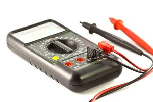
We often need multimeters to measure various electrical values. We use it daily for many technical tasks. A multimeter helps us check voltage, current, resistance, and continuity. From home repairs to professional electrical work, multimeters are indispensable. However, you may feel confused when you first look at the dial and buttons. That’s where understanding multimeter symbols is critical.
On multimeters, each symbol represents a specific function or measurement mode. You must know how each symbol works and how you should measure values. This article introduces the common multimeter symbols. It will teach you how to use those correctly for your project.
What is a Multimeter?
A multimeter is a handheld device used to measure electrical properties in a circuit. Think of it as a “multitool” for electric sectors. Generally, it consists of multiple individual meters that calculate different parameters. From hobbyists and technicians to DIYers, many people use it to observe what is happening in a circuit.
A multimeter can be of two types: an analog multimeter or a digital multimeter. Analog multimeters use a needle to get a reading of different values. It is also vital to check how the values are changing. Although digital multimeters (DMMs) are very common nowadays. It displays each value precisely on digital screens, making it more efficient for beginners and advanced users alike.
Multimeters have a wide range of applications across various sectors. It is a versatile tool that can measure many electrical parameters. Its applications span automotive, electronics, home systems, industrial maintenance, and DIY. This wide application is driven by its accurate, precise readings and range selection.
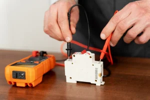
Most people utilize a multimeter for practical tasks. You can use it to measure voltage and check whether a battery is dead or if an outlet is powered. However, inaccurate inspection and results may lead to project failure. But the positive sign is that it delivers flawless, precise results every time.
One of the biggest advantages of using a multimeter is speed and safety. It allows you to troubleshoot problems without guessing, which prevents damage. They are affordable and easy to use, so you can fix your household items yourself.
Typical Multimeter Symbols
Multimeters use universal icons to label their settings. Each multimeter symbol is unique and serves a specific purpose. V~ indicates AC voltage at home outlets, while V⎓ indicates DC battery power. Diode arrows indicate one-way flow, and Ohm (Ω) measures resistance. Lastly, the sound wave icon signifies continuity, and it beeps to state a strong connection.
DC Voltage Multimeter Symbol (V⎓)
The DC symbol on a multimeter looks like a capital V with a plane line and a dashed line above it (V⎓). It stands for direct line current. This symbol is used to test batteries, vehicle electronics, power supplies, and many more.
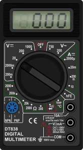
AC Voltage Multimeter Symbol (V~)
The symbol for volts AC also uses a capital V with a wavy line above. The wave typically indicates alternating current, which changes its direction every second. AC multimeter symbols have a wide variety of applications. People use these settings to measure power from wall outlets, industrial equipment, household wiring, and so on.
Resistance Symbols
Ohm (Ω)
Ohm (Ω) is the basic unit of resistance. Every electrical resistance is measured in ohms (Ω). People check the electrical path by assessing these parameters. Moreover, this setting is usually used to verify small components, such as light bulbs or specific resistors.
Kilohm (kΩ)
The kilohm represents 1000 ohms of resistance. It contains a lowercase k followed by the symbol ohm (Ω). This symbol is efficient for measuring mid-range resistance, such as 1kΩ to 10kΩ. You may also see the symbol during testing sensors or electronic circuit boards.
Megaohm (MΩ)
The megaohm represents 1,000,000 Ohms, and the symbols on the multimeter contain a capital M with Ω. This high setting is used to test insulation, industrial appliances, or other highly resistant parts. Sometimes, the scientific method helps to show these large numbers in small quantities.
Continuity Test
Open Circuit
An open circuit means the path does not allow electricity to flow. Simply, the path is broken because there is a gap in the wire or a blown fuse. During reading, the multimeter continuity symbol will either show infinite resistance or OL (open loop). In this state, the meter won’t make any sound.
Close Circuit
A closed circuit is a complete circuit in which electricity passes without any problems. Unbroken loop is another name. When you connect the multimeter for testing, it shows a lower resistance and emits continuous beeps. This signal ensures proper connection and indicates the device has power.
Diode and Capacitance Test
Diode Test
The diode has a symbol of an arrow on a single vertical line. This multimeter mode checks whether the diode works properly and shows a voltage drop in one direction. Usually, a silicone diode has a 0.7 drop, and a germanium diode has a 0.3 drop. For an accurate result, ensure diodes are out of the circuit.
Capacitance Test
The capacitor symbol consists of two parallel lines, often curved. This multimeter symbol indicates the energy stored in a capacitor. The unit is in farads (F) and is generally measured in µF (microfarads). This test helps you avoid weak capacitors in air conditioners or power supplies.
Temperature
Multimeter symbols also contain temperature settings, acting as the thermometer. But to use this as a thermometer, you have to put in a special probe called a “thermocouple”. It uses °C and °F units and is suitable for checking HEVC vents, cooling systems, and overheating components of a computer.
Jacks
Jack plays a crucial role in the multimeter. Jacks are the holes where you need to plug in test leads. There is a COM port dedicated to the black wire. The VΩmA jack is safer for most daily tests. To avoid blowing fuses, set the red lead to the 10A or 20A jack.
Other Buttons
Beyond the main button, some multimeters offer extra features. These features enable better control over each test. Among them, one common button is “hold”. When you press it, the current reading remains locked and paused, even if you move the probe. This button is useful in tight spots, where you may not have proper visibility into the data during work.
Another important button is range. It allows you to select a decimal range for a specific application. However, modern multimeters have an auto-range system, which makes them more ideal for repetitive tasks. There is also a max/min button in a multimeter. Generally, it tracks the highest and lowest readings during the test, great for catching sudden power spikes.
Manual VS Auto Multimeters
Selection depends on how comfortable you are with manual or auto-ranging multimeters. One needs you to know what you want, while the other performs the work for you. Knowing their function helps avoid confusion during screen reading of electrical projects. Both are important and play a vital role in the electronics industry.
Manual Multimeter
A manual multimeter requires the user to select the measurement range. You may see several numbers around each symbol. These changes might vary from list 2V, 20V, and 200V. In this case, carefully select a power level higher than you want. If you are working with a 9 V battery, select the 20V range for accurate reading.
These meters are usually for professionals and provide fast results. They do not have to hunt for the right clip, and numbers appear exactly. Besides, the automatic version is also affordable. If you choose lower ranges, it may show “1” or “OL,” indicating it is overloaded. Therefore, you must move to higher ranges to measure the actual value.
Auto Multimeter
On the other hand, an auto-range digital multimeter is more convenient. The meter features just one icon for each function on the dial. When you select the voltage in this multimeter, it reads data inside the machine. It then aligns with the screen’s decimal point and gives an accurate result with decimal places.
While digital multimeters are slightly helpful, the process is slower. It reduces errors and flaws and improves safety. They are useful for complex geometries and electrical systems. These machines are relatively costlier than manual multimeters. However, the convenience and accuracy often make them worth the cost.
Summary
A multimeter is a commonly used tool for electrical testing and troubleshooting. People widely use it in home repairs, electronics, and professional electrical work.
To understand how each multimeter symbol works, you must understand its working principle. For example, the voltage symbol has various ranges. You must know which range to choose to get the accurate value.
Other symbols, like resistance, continuity, and diode test, help you check wires, components, and circuit connections. Capacitance and temperature symbols allow you to measure specific applications.
If you plan to create custom multimeters for unique projects, UETPCB can help you every step of the way. We are a custom manufacturer of PCB and assemblies. We offer in-house production services, including component sourcing and delivery. If you need further assistance, feel free contact us anytime.