
The first step is to analyze the whole surface of the PCB.
If that’s the case, use a magnifying glass or low-power microscope. Cracks or stains in any solder ought to be noted. Assess all holes. When none-plated through holes have been given, make certain this is the situation on the plank. Poor plating through pockets can lead to a brief circuit between layers and lead to whatever you need to earth, VCC or both together.
When the brief circuit is actually severe and causes the part to reach a vital temperature, you may actually see burn areas on the printed circuit board. They could be little, but they’ll turn brown rather than the typical green solder. In case you’ve got several boards, a burnt PCB assembly will be able to help you narrow down the region in a specific place without needing to power another plank, forfeiting the hunt area. Regrettably there were no burns on the circuit board, just unfortunate palms checking to determine whether the IC was still overheating.
Some brief circuits will happen within the circuit board and won’t create a burn stains. This also suggests they won’t be seen from the surface. Here, you’ll need different techniques to find short circuits at the PCB.
Working with an infrared thermograph will be able to help you find regions that generate a good deal of heat.
Whether an active element isn’t seen from a hot place, a PCB short circuit may occur even when the brief circuit occurs between the interior layers.
Short circuits normally have a greater resistance than normal pipes or pipes pads since they don’t have any advantage of optimization at the layout (unless you truly wish to discount rule checking).This immunity, together with the naturally large current generated from the direct relation between the power source and the floor, means the rake from the brief circuit of the PCB will heat up. Begin with the lowest present you can utilize. Ideally, you’d observe a brief circuit and cause more harm.
Along with the very first step of assessing a circuit board using a trustworthy eye, there are numerous different methods in which you may locate the possible reason for a PCB short circuit.
Other different methods of inspecting PCB short circuit
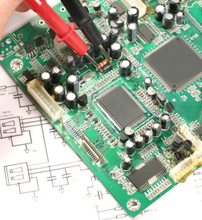
To check the circuit board if short circuit or maybe not, you want to look at that the resistors between different pads at the circuit. When the visual inspection doesn’t reveal any clues regarding the place or cause of the brief circuit, then catch the millimeter and attempt to follow the physical place on the printed circuit board. The millimeter strategy has received mixed reviews in the majority of digital forums but monitoring evaluation points can help you determine what the issue is.
You’ll require an excellent millimeter with great sensitivity, which can be simplest if it’s a buzzer role to alert you if short circuits have been detected. By way of instance, if the resistors between adjacent wires or pads on a PCB are quantified, high resistors must be quantified.
When the resistor between the two conductors to be quantified in another circuit is quite low, the 2 conductors might be bridged either externally or internally. Notice that bridging two adjacent pads or wires using an inductor (by way of instance, within an impedance matching network or different filter circuit) can lead to very low resistance readings since the inductor is merely a spiral conductor. But if the 2 conductors on the board are far apart and the immunity you browse is small, there’ll be a bridge somewhere on the plank
Especially significance is short circuits between floor through-holes or linking formations. A multilayer PCB with an inner layer includes a return route through the meeting close to the through-hole, which gives you a handy place for assessing the rest of the through-holes and pads onto the board surface coating. Place one probe on the floor link and get the other probe on the opposite conductors.
The exact same ground connection will even exist in other places on the board, meaning if every probe is touched to 2 distinct through-holes, the scanning will probably be little. Look closely at the design when doing so, since you don’t want to confuse a brief circuit for a frequent ground connection. The rest of the ungrounded, bare conductors will have a higher resistance between the frequent ground connection and also the conductor itself. If the value read is reduced and there’s absolutely no inductor between the conductors in question along with the floor, the part might be broken or short circuited.
Assessing for small circuits in parts also entails measuring resistors with a millimeter. If visual inspection doesn’t show extra solder or sheet metal between the pads, then a brief circuit may be formed in the interior layer involving the pads/pins on the meeting. A brief circuit may occur involving the pads/pins on the meeting as a result of poor soldering. This is only one reason PCB assembly should experience DFM and design rule checks. Close soldering and perforations may short-circuit unintentionally during production.
Here, you want to assess the resistance between the pins on the IC or connector. Adjacent pins are especially simple to short circuits, but these aren’t the only areas where short circuits may happen. Assess that the resistances between the pads/pins are relative to one another and the earth connection has a low resistance.