
Introduction
You may have created your rigid FR4 multilayer PCBs by now and are satisfied with their performance. You understand their construction (FR4, Copper Layers, Prepreg, etc.) and probably know how to order and create them online. However, you realize that your project’s interconnections are increasingly getting more complicated and space-constrained. You need something more than just standard connectors to connect your boards.
Here is where Flex or Rigid-Flex PCBs may come into play.
What are Flex PCBs?
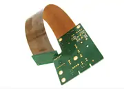
Flex PCBs are flexible circuit layouts that can help your space-constrained projects. Imagine installing keypads or LCDs on a front panel where space and clearance are critical (like in smartphones or laptops). Here, Flex PCB layouts can help. You can use Flex PCBs on non-stationary parts of your projects, such as sliding keypads or flip casings. Below are common stack-up configurations and materials used on Flex PCBs
Example Flex PCB Stackup Configuration
One Layer Flex PCB
- Coverlay (Protector)
- Adhesive
- Copper Layer
- Adhesive
- Polyimide (Base Material)
- Stiffener (optional)
Two Layer Flex PCB
- Coverlay (Protector)
- Adhesive
- Top Copper Layer
- Adhesive
- Polyimide (Base Material)
- Adhesive
- Bottom Copper Layer
- Adhesive
- Coverlay (Protector)
- Adhesive
- Stiffener (optional)
Coverlay is a Flex PCB’s protection layer, much like solder masks do on rigid PCBs. Manufacturers typically use a plastic material (Polyimide) for this layer. The adhesives are there to bond the layers on top of one another. The Copper layer is where you can route your tracks (much like on an FR4 PCB). This layer is usually made of rolled-annealed copper foil so that it can bend repeatedly.
The base material having flex characteristics is plastic material called Polyimide (same as the coverlay). This material helps in the bending and curving of your board. Stiffener materials can be added at the ends of a flex PCB (FR4 or Polyimide itself) so that users can conveniently insert the ends into a connector.
Note that Flex PCBs can be single or multiple layers. If you want multiple layers, you can repeat stacking up the coverlay, copper, and polyimide layers.
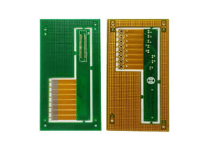
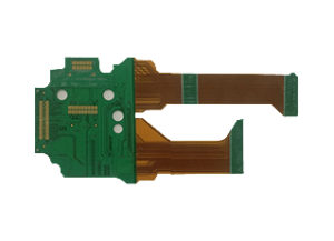
What are Rigid-Flex PCBs?
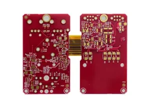
Flex PCBs are great, but combining flex and rigid PCBs makes things more interesting. Rigid-Flex PCBs provide a connector-free solution for your projects. With this, you no longer need FPC connectors. This combination means fewer manual connections during assembly and a reduced BOM list. You can also create rigid-flex PCBs on a single panel assembly, instantly freeing you of other time-consuming assembly tasks.
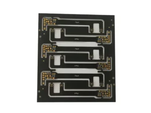
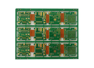
Since rigid-flex PCBs have both flex and rigid parts, their stackup configuration is quite unique. Below is a 4-layer rigid-flex stackup configuration.
Rigid-Flex PCB Stackup Configuration
4 Layer Copper Rigid PCB Side
- Solder Mask
- Top Copper Layer
- FR4 (base material)
- Prepreg ———————> joining line
- Inner Copper Layer
- Polyimide
- Inner Copper Layer
- Prepreg———————->joining line
- FR4 (base material)
- Bottom Copper Layer
- Solder Mask
2 Layer Copper Flex PCB Side
- Coverlay (Protection)————->joining line
- Coverlay Adhesive
- Inner Copper Layer
- Polyimide (Base Material)
- Inner Copper Layer
- Coverlay Adhesive
- Coverlay (Protection)————>joining line
Above, you’ll see both rigid and flex stack-ups in a one-panel assembly. The rigid PCBs should be on both ends of the flex part, which is in the middle of these rigid PCBs. How do these PCBs join each other? It’s by the rigid PCB voiding space on its supposed inner layers. The inner copper layers of the rigid PCB become the flex PCB copper layers. In essence, the flex PCB becomes one with rigid PCB, only having the prepreg of the rigid PCB join the coverlay and coverlay adhesives.
How to Start Creating a Flex PCB?
Using any PCB design software with layer parameters, you can create a flex PCB. As a PCB designer, you have to assign the layer structure of your PCB much like any standard PCB. These layers include the copper (top, bottom, or inner), solder mask (top and bottom), solder paste (top and bottom), silkscreen (top and bottom), board outline, and others. After that, you can continue to route the copper layers of your flex board. Flex boards have special design considerations since they have a thin plastic structure.
Sending your Design to a Manufacturer
After designing and checking your boards, you can create manufacturing outputs like any standard PCB. After that, you could send them to your PCB fabricator.
It’s up to your PCB manufacturer how they will process and manufacture your flex board. With this, you must communicate and relay to them what you expect from your output. Such items include FPC thickness (board thickness), stiffeners, coverlay (solder mask) color, surface finish, and others.
How to Specify a Rigid-Flex PCB?
Although a rigid-flex PCB has a unique stack up and shape, you can design them like a standard PCB on your PCB design software. The critical thing to consider is relaying the proper stack up and form factor of the rigid-flex PCB you want to your manufacturer. With this, you can utilize the edge cut or board outline and other user layers on your PCB design software. This process can define the boundaries of the rigid and flexible part of your board.
For example, you can define the flex part (which also covers your board outline) on your board outline or edge cuts layer. Next, determine your rigid board boundaries using one user layer. It’s up to you to decide which style you’ll use. What’s important is that you’ve relayed the boundary and stack-up information to your PCB manufacturer.
Conclusion
Flex and Rigid Flex PCBs are a great way to miniaturize, mobilize, and save space in your projects. Knowing their structure and how manufacturers form them is the first step to familiarize yourself with them. Designing flex and rigid-flex PCBs is no different than making rigid FR4 PCBs, except that you’ll have to verify some vital parameters and processes explicitly. These things include your stack up, board type boundaries, operation process, and materials to your PCB manufacturer.