
PCB, or printed circuit board, is everywhere. It is a critical part of every modern electronic device. It serves as the backbone of the device and makes it possible for electronic components to fit together smoothly. When we explore PCBs more, we find a wide range of variations. HDI PCB is one of them.
PCBs are essential in electronic devices. They provide a stable place to put and connect electronic parts, and they aim for reliability and stability in electronic operation. Today, we will talk mainly about HDI PCBs. We will distinguish their properties and applications from ordinary PCBs. We hope you can acquire sufficient knowledge and use it to select the right PCBs for your project.
What is a High-Density Interconnect PCB?
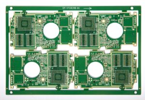
HDI PCB stands for High-Density Interconnector Printed Circuit Board. This kind of PCB is one of the highest-tech products available in the electronics business. Engineers developed this type to overcome the limitations of ordinary PCBs. You can understand why it is necessary if you explore its structure.
A HDI board is made up of many layers that are stacked on top of each other. It also has advanced technologies for linking items. It makes it possible to put more components on a board than with a regular PCB. So, they offer better signal stability while also being smaller and lighter. It improves electrical function overall.
HDI PCBs make electronic gadgets smaller by fitting more parts into a smaller space. They also offer better performance and usefulness.
HDI PCBs are often used in computers, smartwatches, smartphones, and other devices. All of these are new technologies that people use today. One more place where they might be helpful is in medical equipment. HDI PCB technology is used in modern car systems for things like ADAS. They are all meant to be used in these areas to make things smaller and work better.
1. Advantages of HDI PCB
- 1.1 Compact HDI Board Design
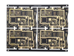
One significant benefit of HDI PCB is that it packs electronic components into small spaces. Microvias and fine-pitch tracks are some of the complex route methods it uses. These methods allow parts to be put together in tighter arrangements, making the PCB smaller overall.
- 1.2 More Component Density
Another critical benefit of HDI PCBs is that they can hold more components compared to regular PCBs. Because they have microvias and multilayers, designers can fit more parts into a smaller space, making tech gadgets more practical and effective.
- 1.3 Advanced manufacturing
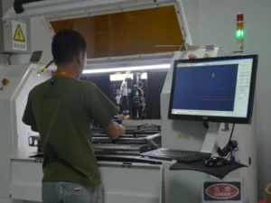
HDI circuit board needs new methods and techniques for production. You already know that it helps make complex designs with high component density. Some of these techniques are laser drilling, sequence lamination, and others. It is also common for HDI PCB fabrication to need specific materials and tools.
- 1.4 Capable of withstanding higher frequency
HDI PCBs can handle higher frequencies without losing the purity of the signal. Reliable signal transfer is possible because of the small size, low signal loss, and distortions. Because of this, HDI technology works well for operations that need to send data quickly. Telecommunications tools, networking devices, and high-performance computer systems are all well-known examples.
2. Limitations of HDI PCB
- 2.1 Relatively Expensive
HDI PCB production needs cutting-edge materials and technologies. The cost of production is higher for HDI circuit boards than regular PCBs. As such, this PCB might not be appropriate for applications with strict financial requirements.
- 2.2 Increased Complexity in design and Manufacturing
On the other hand, HDI PCB technology often comes with increased Complexity in design and manufacturing processes. It has microvias and tight routing constraints. As a result, designing layouts for HDI circuit boards demands specialized expertise and tools.
What is Ordinary PCB?
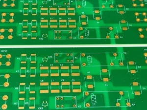
An ordinary PCB is also known as a conventional or standard PCB. It is the foundational technology in making electronics. It usually has one or two layers of non-conductive substrate material.
In most cases, fiberglass-reinforced epoxy and conductive copper traces are used. Conductive copper traces are usually etched onto one or both sides of the PCB. You know, these copper traces are the pathways for electrical signals.
Standard PCBs are used in a lot of different fields. PCBs can be found in everything from home technology to car systems. Designing and making an ordinary PCB is easy. This makes them good options for many uses because they are cost-effective. Standard PCBs are easy to put together. It can hold common electrical parts.
TVs, radios, and computers are all examples of things that use regular PCBs. They can also be found in control screens and sensors used in factories. Regular PCB boards, such as the ECU and dashboard screens, are used for car parts. They are also used in everyday in-home products like washing machines and microwave ovens.
1. Advantages of Ordinary PCB
- 1.1 Lower cost of manufacturing
Standard PCBs are preferred because they are cheaper to make. They usually have easier patterns and ways of making them. It helps explain why it costs less to produce than HDI PCB board.
- 1.2 Simplicity in design and manufacturing
Another great thing about regular PCBs is that they are easy to build and make. Most of the time, these PCBs have fewer layers and easier ways to join them, making them easy to plan and develop. As a result, work goes faster when the plan is easier.
- 1.3 Availability of materials and manufacturing processes
The ingredients used to make regular PCBs are easy to find in the business world. Standard materials, such as FR4, and traditional methods of making things are easy to get. This speeds up production by cutting down on wait times.
- 1.4 Suitable for basic electronic applications
This type of PCB is straightforward and flexible. It can perform several simple electronic tasks. Simple circuit designs and moderate component densities work well with these PCBs, making them perfect for industrial controls, home technology, and appliances.
2. Limitations of Ordinary PCB
- 2.1 Limited density of components
Standard PCBs are cheap and easy to make but don’t have much room for parts. This limitation comes from most PCBs having only one or two sides. It limits the amount of room that can be used to assemble parts.
- 2.2 Reduced signal integrity, especially at higher frequencies
Standard PCBs usually have a lower ability to keep signal integrity. This happens especially when working at higher levels. The comparatively simple layout and construction of a typical PCB may cause data lines to be longer. Therefore, regular PCBs are not utilized in high-frequency applications like computers.
- 2.3 Larger size and Weight of devices compared to HDI PCBs
Normal PCBs are bigger and heavier than HDI PCBs, mainly because the components aren’t very dense. Ordinary PCBs also need a bigger space to fit the same functions as HDI PCBs. Larger and heavier gadgets can change how a product looks, and overall efficiency and flexibility are also affected.
HDI PCB vs Ordinary PCB: What’s the difference?
This table shows many changes between HDI PCBs and regular PCBs. We looked at several factors that clearly distinguish these two common types of PCBs.
| Aspect | Higher Density Interconnect PCB | Ordinary PCB |
| Density of components | High | Low |
| Signal integrity | Excellent | Moderate |
| Size & Weight of devices | Compact & lightweight | Larger & heavier |
| Manufacturing cost | Higher | Lower |
| Manufacturing complexity | Complex | Simple |
| Suitability for high-speed applications | Excellent | Limited |
| Layer count | Typically, higher | Typically, Lower |
| Signal Routing | More efficient due to a higher layer count | Less efficient due to fewer layers |
| Thermal management | Better heat dissipation due to improved design | Limited heat dissipation due to simpler design |
| Frequency limitations | Suitable for high-frequency applications | Limited suitability for high-frequency applications |
| Design flexibility | Greater flexibility in layout and routing | Limited flexibility due to design constraints |
| PCB cost-effectiveness | Maybe cost-effective for high-performance applications | Cost-effective for basic electronic applications |
Why is HDI PCB Better?
HDI PCBs are better than regular PCBs in several ways. Because of these pros, HDI PCB is better than standard PCB.
1. An HDI-printed circuit board can fit more parts than a regular one, improving its functioning.
2. It reduces signal loss and confusion from electromagnetic waves, resulting in better performance.
3. HDI technology lets you get a better trance and smaller vias. This makes impedance control and output speed better.
4. This technology lets you do more in a smaller space. This means that it is smaller and lighter.
5. For high-speed tasks, HDI PCB is the best choice.
Overall, the HDI PCB is the best choice based on its performance and the size of the electronic gadget. If your project requires simple performance, you should choose a regular PCB.
Frequently Asked Questions
Q1. Do PCB boards featuring blind holes commonly fall under the category of HDI boards?
Yes, PCB boards featuring blind holes are HDI boards. Blind vias are a common feature in HDI PCBs. They allow for increased component density and enhance routing capabilities.
Q2. What is the best type of PCB?
The best type of PCB usually depends on the application’s specific requirements. However, HDI PCB is often ideal for high-density and high-performance applications. Conversely, ordinary PCBs are widely used for general-purpose electronics.
Q3. What is the difference between HDI and FR4?
HDI PCBs feature advanced technologies for increased component density and signal integrity. FR4 is a substrate material commonly used in PCBs because of its affordability and versatility.