
You may have wondered how a small laptop can process and work with large amounts of data. Or perhaps you have wondered how tiny computer processors are able to perform complex tasks. What are logic gates, by the way? And how do XOR and XNOR gates really work? If so, today’s discussion is for you.
Logic gates are the core foundation of digital logic units. They are used to build various computing, processing, and control devices.
Understanding Basic Logic Gates
Before understanding an XOR and XNOR gate, you must first understand what logic gates are. Well, they are a specific type of gate that processes one or two input signals and determines an output signal.
In general, three basic logic gates are used in digital circuits: AND, OR, and NOT. They mainly work with binary values, 0 and 1, and produce an output based on the inputs you apply. In XOR and XNOR gates, you will need them as the foundation of the structure.
AND Gate
An AND gate produces an output of 1 only when all inputs are 1. If any input is 0, the output becomes 0. In a two-input AND gate, let’s assume the inputs are A and B, and the output is Y. The AND gate follows the rule: Y = A · B.
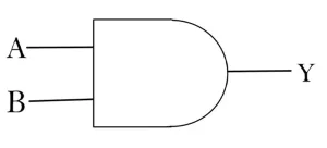
For example, if A = 1 and B = 1, the output is 1. If A = 1 and B = 0, the output is 0. Therefore, the output becomes 1 only when both inputs are 1.
|
A |
B | Y |
|
0 |
0 | 0 |
| 1 | 0 |
0 |
|
0 |
1 |
0 |
| 1 | 1 |
1 |
OR Gate
An OR gate produces an output of 1 when at least one input is 1. The output is 0 only when all inputs are 0. For a two-input OR gate, A and B are the inputs, and Y is the output. The OR gate follows this rule: Y = A + B.
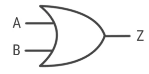
For example, if A = 1 and B = 0, the output is 1. If A = 0 and B = 1, the output is also 1. When both inputs are 1, the output remains 1. Only when both inputs are 0 does the output become 0.
|
A |
B | Y |
|
0 |
0 | 0 |
|
1 |
0 |
1 |
| 0 | 1 |
1 |
| 1 | 1 |
1 |
NOT Gate
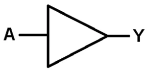
A NOT gate, on the other hand, works differently from AND & OR gates. It has only one input and one output. It actually reverses the input. For example, if the input is 0, the output becomes 1. If the input is 1, the output becomes 0. The NOT gate can be represented as: Y = Ā. Therefore, a NOT gate is also called an inverter because it inverts or reverses the input signal.
|
What is an XOR Gate?
An XOR gate, or Exclusive OR gate, is a special logic gate used in digital circuits. It produces an output of 1 when its inputs are different. On the other hand, when both inputs are the same, the output is 0.
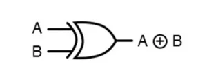
The name XOR typically comes from the word “Exclusive OR.” A normal OR gate produces 1 when one or both inputs are 1. On the other hand, a NOR gate produces 1 when both inputs are 0. An XOR gate is more selective. It produces 1 only when exactly one input is 1.
For a two-input XOR gate, the inputs are usually represented by A and B, while the output is Y.
Y = A ⊕ B
Here, the symbol ⊕ represents the XOR operation. The gate schematic is generally used for the XOR operation. If we expand this gate symbol, we can see that it consists of several NOT, AND & OR gates.
XOR Gate Circuit Diagram & IC Working Principle
An XOR gate can be built using two NOT gates, two AND gates, and one OR gate. The diagram shown above shows how the basic gates are connected to create XOR behavior.
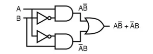
The circuit has two inputs, A and B. These inputs are sent through different paths to produce two intermediate AND-gate outputs.
First, A passes directly to the AND gate, and B passes through a NOT gate. Therefore, the upper AND gate receives A and B̅. Therefore, the output here is AB̅. On the other hand, the bottom AND gate gets A, which passes through a NOT gate, and B directly to the AND gate. Therefore, the result becomes A̅B.
Finally, the outputs of both AND gates are connected to an OR gate. The OR gate combines these two signals and produces the final XOR output.
Y = AB̅ + A̅B
XOR Truth Table
|
A |
B | Y = AB̅ + A̅B |
|
0 |
0 | 0 |
|
0 |
1 |
1 |
| 1 | 0 |
1 |
| 1 | 1 |
0 |
So, according to the ex or gate truth table, the output becomes 1 when either A is 1 and B is 0, or A is 0 and B is 1. If both inputs are the same, the output is 0.
What is an XNOR Gate?
An XNOR is another special logic gate in a digital circuit. It is an exclusive NOR gate that produces an output of 1 when its inputs are the same. If the inputs are different, the output becomes 0. Therefore, an XNOR gate performs just the opposite operation of an XOR gate.
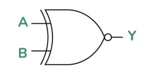
Once again, for a two-input XNOR gate, the inputs are usually represented by A and B. Y can represent the output.
The symbol ⊙, or the bar above A ⊕ B, represents the XNOR operation. An XNOR logic gate can also be understood as an XOR gate followed by a NOT gate. Since an XOR gate produces 1 when the inputs are different, the NOT gate reverses this output. As a result, XNOR only produces 1 when the inputs are equal.
XNOR Circuit Diagram & IC Working Principle
The XNOR gate can be built using two NOT gates, two AND gates, and one OR gate. The circuit shown uses the inputs A and B and creates two separate logic paths.
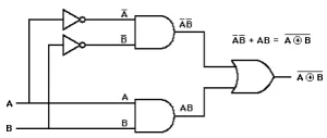
First, input A passes through a NOT gate, producing Ā. On the other hand, input B passes through another NOT gate, producing B̅. These inverted signals enter the upper AND gate and produce ĀB̅. At the same time, the original inputs A and B are sent directly to the lower AND gate. It produces the output AB.
Finally, the outputs of both AND gates are connected to an OR gate. The OR gate combines ĀB̅ and AB. It finally produces the XNOR output ĀB̅ + AB.
XNOR Truth Table
|
A |
B | Y = ĀB̅ + AB |
|
0 |
0 | 1 |
| 0 | 1 |
0 |
| 1 | 0 |
0 |
| 1 | 1 |
1 |
So, from the table, we can see that the output is 1 when both inputs are the same. On the other hand, when both inputs are 0, the output is 1. When both inputs are 1, the output is also 1. If one input is 0 and the other is 1, the output becomes 0.
XOR vs XNOR Gate
The main difference between XOR and XNOR gates is their output condition. An XOR gate produces 1 when the inputs are different. On the other hand, an XNOR gate produces 1 when the inputs are the same.
|
A |
B | XOR | XNOR |
|
0 |
0 | 0 | 1 |
|
0 |
1 | 1 |
0 |
| 1 | 0 | 1 |
0 |
| 1 | 1 | 0 |
1 |
Applications of Logic Gates in Digital Circuits
Logic gates are typically the building blocks of digital circuits. They mainly process binary signals, which are represented by 0 and 1. With the help of different logic gates, you can create complex electronic systems. You can use them for arithmetic, data processing, and memory, or even control systems.
Digital Arithmetic Circuits
Logic gates are widely used to perform arithmetic operations on binary numbers. In general, AND, XOR, and OR gates are addressed in this case. In digital circuits, a half adder adds two binary bits. On the other hand, a full adder adds three bits, including a carry. These circuits are mainly necessary for calculators, computers, and processors.

Data Selection & Routing
Logic gates also help select and control the flow of digital data. They are widely used in multiplexers and demultiplexers. A multiplexer typically selects one input from several signals. On the other hand, a demultiplexer sends one input to a selected output.
Data Storage and Memory
Logic Gates are typically used to build circuits that can store binary information. You can think of latches and flip-flops. They can store either 0 or 1. These circuits are the basic parts of registers and memory systems.
Comparison of Binary Values
Logic gates can also compare binary values. You can use XOR gates to check whether two bits are different. You can also use AND, OR, and NOT to create digital comparators. These circuits are very useful for checking digital data.
Error Detection and Data Checking
Logic gates can also help detect errors in the digital data. You can use an XOR gate to generate and check parity bits. They can identify some data transmission errors. This mainly improves the reliability of digital systems.
Control and Decision-Making Circuits
Logic gates are also used to make simple digital decisions. They can control whether a signal is allowed to pass. For example, an AND gate needs multiple conditions to be true. On the other hand, OR gates can allow any one of several conditions to activate a circuit.
Digital Counters and Timing Circuits
You can also use logic gates to build digital counters and timing circuits. Flip-flops are connected to count pulses. These circuits can track events and generate timing signals. They are common in clocks, timers, and digital devices.
Computer Processors and ALUs
Another crucial use of logic gates is in computer processors. They are used to build arithmetic logic units (ALUs), which perform the arithmetic and logical operations in the processor. These operations are necessary for processing data and running computer programs.
Conclusion
XOR and XNOR gates are important logic gates in digital electronics. XOR produces 1 when its inputs are different. On the other hand, XNOR produces 1 when its inputs are the same. Both gates are constructed from multiple basic logic gates.
XNOR and XOR gates are widely used in arithmetic circuits, data checking, comparators, and so on. This article explains how XOR and XNOR gates work and their truth tables. If you have any questions regarding circuit-related problems, please get in touch with us.