
A potentiometer is a crucial device that helps in several circuits and systems. Whether you are designing an audio amplifier, calibrating a sensor, adjusting LED brightness, controlling motor speed, or creating an analog user interface, a potentiometer provides an effective and fast way to control and adjust the current and voltage values.
However, wiring a potentiometer is essential for its seamless functionality. Wiring looks simple and efficient, but it can be technical if you are a newbie and don’t know the right terminals.
We will discuss how to hook up a potentiometer and understand various steps and components. Let’s know!
What is a Potentiometer?
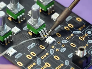
A potentiometer is a three-terminal variable resistor with a resistive track and a movable contact. Rotation of the potentiometer knobs can help adjust the voltage and resistance values in a circuit.
Unlike fixed resistors, a potentiometer makes the current and resistance values adjustable and variable.
Common applications of a potentiometer include:
- Volume controls
- Light dimmers
- Sensor calibration
- Motor speed adjustment
- Instrument tuning
- Reference voltage generation
- User interface controls
- Industrial equipment calibration
Understanding Potentiometer Pinout
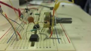
Many potentiometers have three terminals with the following configurations.
- Pin 1 is often a fixed terminal and is at one end of the resistive track.
- Pin 2 is often an adjustable output called the wiper.
- Pin 3 is also a fixed Terminal and is available at the opposite end of the resistive track.
The outer terminals remain fixed and constant while the center pin moves.
As the knob moves:
- Wiper moves toward Pin 1
- Resistance between Pin1 and Pin2 decreases
- Resistance between Pin2 and Pin3 increases
The total resistance between Pin 1 and Pin 3 remains constant and fixed due to fixed terminals.
Types of Potentiometers
There are different types and configurations of potentiometers. Here are a few types listed easily
.
- Rotary Shaft often provides rotational motion control and is commonly used in audio and electronics.
- Slide potentiometers have a linear slider and are useful for audio mixers.
- Trimmer (Preset) has a Small adjustable knob and is suitable for PCB calibration.
- Multi-turn potentiometers have high precision and are ideal for instrumentation.
- Digital potentiometers are controlled electronically and are part of embedded systems.
Wiring a Potentiometer as a Voltage Divider
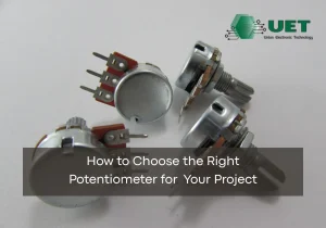
The most common configuration for wiring a pot is as a voltage divider. All three terminals are used to configure and use it in this system.
The connections are as follows:
- Pin 1 → Ground
- Pin 3 → Supply Voltage
- Pin 2 → Output Voltage
Shaft position changes the output voltage and has a significant impact. Here are a few applications of the potentiometer as a voltage divider.
- Analog inputs
- ADC reference adjustment
- Brightness control
- Variable power supplies
- Position sensing
Wiring a Potentiometer as a Variable Resistor
A variable resistor is also called a rheostat. Instead of three terminals, this configuration requires only two: one wiper terminal and a fixed terminal.
It helps control the resistance and is suitable in the following applications.
- LED current adjustment
- Motor speed control
- Current limiting
- Heater control
- Laboratory testing
Choosing the Correct Potentiometer Value
Often, 10kΩ is the most commonly used resistance value. However, there can be many other values listed below.
| Resistance | Typical Applications |
| 1kΩ | High-current circuits |
| 5kΩ | Industrial controls |
| 10kΩ | Arduino, sensors |
| 50kΩ | Signal adjustment |
| 100kΩ | Audio circuits |
| 500kΩ | Amplifiers |
| 1MΩ | High-impedance circuits |
Potentiometer Wiring Examples
We have added a few potentiometer wiring examples listed below.
Arduino Analog Input
Arduino analog input has the following terminals and connections.
- Pin1 → GND
- Pin2 → A0
- Pin3 → 5V
When you rotate the knob, it changes the values between:
- 0
- 1023
It is ideal for the following applications and conditions.
- Servo control
- Menu navigation
- Speed control
- Sensor simulation
LED Brightness Control
Potentiometers help control the brightness and provide a quality control voltage for the PWM controllers.
Typical uses of the potentiometers include:
- Decorative lighting
- Instrument panels
- Display backlights
- Control knobs
Audio Volume Control
Many audio Volume Control Systems also use the potentiometer to adjust the settings.
The wiring system is as follows:
Input → Potentiometer → Amplifier
The wiper feeds the amplifier input and helps streamline the volume changes.
Sensor Calibration
Industrial sensors require calibration. Thanks to the potentiometer, the following sensors can be calibrated.
- Pressure sensors
- Temperature transmitters
- Flow meters
- Analog instrumentation
Testing A Potentiometer
A digital multimeter is a crucial tool for testing a potentiometer. Here are three main steps to test a potentiometer.
Step 1: Measure Between Two Outer Terminals
First, measure the resistance between the two outer pins. Since it is constant, it equals the rated resistance value. For example, a 10kΩ potentiometer gives an expected reading of approximately 10kΩ.
Step 2: Measure Between Wiper and Pin1
Now you should measure the resistance between the wiper and Pin1. It should technically change smoothly and provide accurate values.
Step 3: Measure Between Wiper and Pin3
Now measure between the wiper and Pin3. Remember, values should change inversely to the previous measurements.
Any sudden jumps, dead spots, or open circuits indicate damaged or worn potentiometers.
PCB Design Tips for Potentiometer
A well-designed PCB offers accurate values and long-term reliability.
Place the Potentiometer Near the Circuit It Controls
Placing the potentiometer near the circuits has several benefits. For example:
- Lower noise
- Reduced voltage drop
- Better signal integrity
- Fewer EMI issues
Separate Analog and Digital Traces
Sometimes analog circuits are sensitive. Digital traces can interfere with the sensitive analog circuits and cause issues. Therefore, you should maintain a distance between:
- Clock lines
- PWM traces
- High-current paths
- Analog wiper signals
Use a Solid Ground Plane
Ground planes have several benefits in reducing the following issues.
- Noise
- Ground loops
- Electromagnetic interference
It is crucial for audio and precision measurement circuits.
Route the Wiper Trace Carefully
The wiper is the most crucial terminal. You should keep the wiper trace:
- Short
- Away from switching regulators
- Away from relays
- Away from high-current traces
Select Proper Mounting Style
There are different mounting styles, such as:
- Through-hole
- Surface mount
- Panel mount
- Right-angle mount
Always prefer the right mounting style based on:
- Mechanical strength
- User accessibility
- Manufacturing method
Allow Mechanical Clearance
Mechanical interference is a major issue if your rotating shaft doesn’t offer the right clearance. You should check the following options for mechanical clearance:
- Knob diameter
- Panel thickness
- Mounting hardware
- Nearby components
Consider Environmental Protection
For harsh environmental conditions, you need to improve the reliability of the potentiometers. Such environmental conditions demand:
- Sealed potentiometers
- Dust-resistant designs
- Waterproof housings
- Corrosion-resistant terminals
Common Wiring Mistakes
When wiring a potentiometer, you might make a few mistakes related to wiring and connections. Here are a few mistakes with their solutions listed.
Using the Wrong Potentiometer Value
A compatible potentiometer value helps choose the right options. The wrong selection can cause system failure. To avoid failure, we have added a few tips.
- Choose the resistance value recommended in the circuit design.
- Use 10kΩ for most microcontroller analog input applications unless specified otherwise.
- Consider the input impedance of the connected circuit before selecting a value.
Wiring wrong pins
Outer pins are constant, while the wiper provides the adjustability features. You should choose the right wires and connections according to your pin systems.
Here are a few tips.
- Identify the center pin as the wiper before making connections.
- Verify the pinout using the manufacturer’s datasheet.
- Test the pin configuration with a multimeter if you are unsure.
Skipping Circuit Testing
Testing is essential to know all the values and parameters before the operations. If you don’t test the circuit, the wrong combination can cause accidents and may damage your system components.
Here are a few tips to avoid such issues:
- Measure the total resistance between the two outer terminals.
- Rotate the shaft and ensure resistance changes smoothly.
- Double-check all wiring connections before applying power.
FAQs
- Why is my potentiometer output unstable?
If you are experiencing unstable output values, it can be due to poor wiring, electrical noise, a worn wiper, incorrect grounding, long signal traces, or exceeding the component’s electrical ratings.
- What is the difference between a linear and a logarithmic potentiometer?
A linear potentiometer changes resistance values uniformly. A logarithmic potentiometer follows the logarithmic curves and changes the values according to the curves.
- What is the most common potentiometer value?
10kΩ is the most common potentiometer value used globally. It is often used in microcontrollers, sensor interfaces, and general-purpose voltage divider circuits.
- Can I use only two pins of a potentiometer?
Yes. Switching a potentiometer to two pins converts it into a rheostat. You should have the wiper and one outer terminal in such a case.
- Which pin is the output on a potentiometer?
The center pin is an adjustable output terminal in a three-pin potentiometer. It is often called the wiper.
Conclusion
A potentiometer is a reliable tool, but you must understand all of its components and know exactly how it works. Consider the proper configuration, use it correctly as a voltage divider or rheostat, and select appropriate resistance values to make the circuit systems more flexible. For proper wiring of a potentiometer, you must know the key steps and tips from our experts.
Are you looking for the PCB or related services? UETPCB is a professional PCB manufacturer that delivers quality and after-sales support. We help design PCB prototypes and assemble different components. Contact our experts regarding your project right away!