
This article focuses on pcb soldering for beginners and explains how to solder various components using several different techniques. Although pcb soldering may seem daunting at first, once you give it a try, you will find that it is easy to do in most applications.
How to solder circuit boards
Manual solderingtools
Electric iron, ferrochrome frame
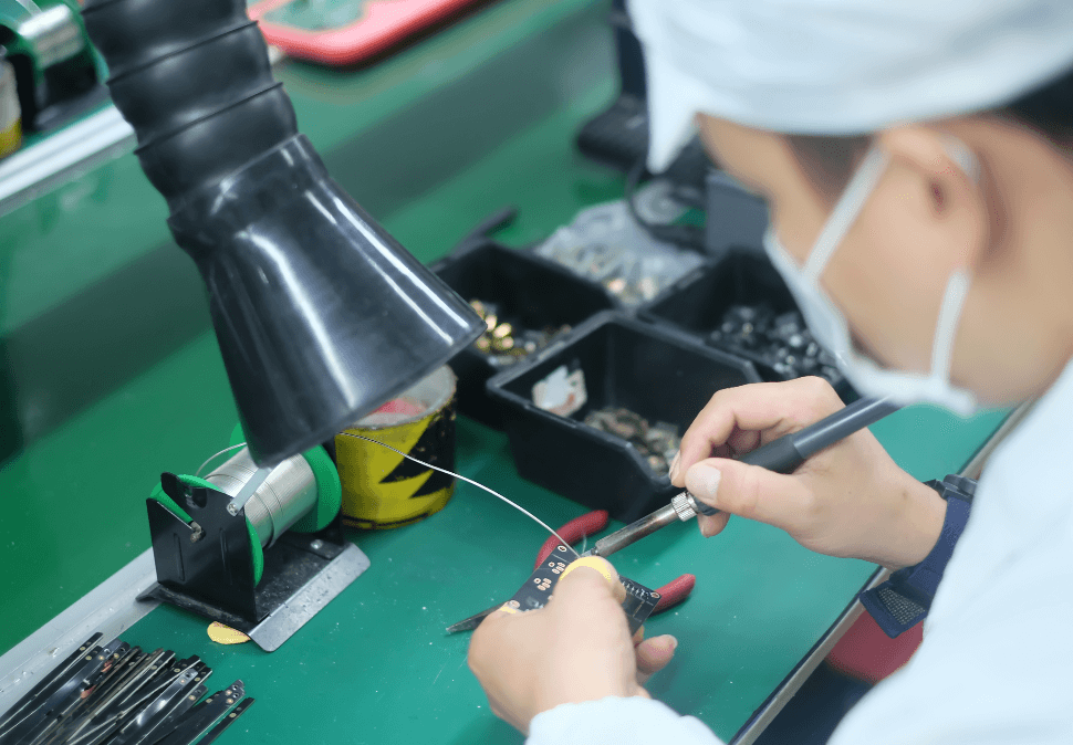
A soldering iron is a handheld tool plugs into a standard 120V AC outlet and heats up with melted solder around an electrical connection. For beginners, it is recommended that you use a pen soldering iron in the 15W to 30W range. Most soldering irons have interchangeable tips that can use for different soldering applications. Be very careful when using any soldering iron, as it can heat up to 896′ F, which is very hot.
A soldering iron holder is very practical and convenient. The holder helps prevent the hot soldering iron tip from coming in contact with flammable materials or causing accidental injury to your hands.
Conditions of soldering
Components must be weldable
The soldering pads of the component shall be kept clean
Appropriate using the flux
Appropriate soldering temperature
Suitable soldering time
The solder
Tubular solder wire
Antioxidant solder
Silver solder
Solder paste
Selection of flux
Flux can improve the soldering performance, common fluxes are:
Solder paste/oil: Solder circuit boards is corrosive and can not be used to sold electronic components and printed circuit boards. After soldering, the residual solder paste/oil should be cleaned up.
Rosin:Rosin should be used as a flux when the pins of the components are tin-plated.
Rosin solution: If the printed circuit board has been coated with rosin solution already, then there is no need to use flux when soldering.
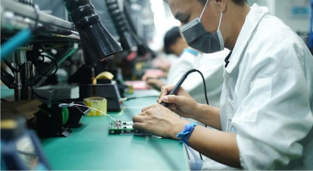
Soldering steps
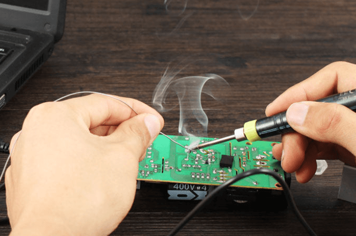
Prepare for soldering: In the process of solder circuit boards,the left hand holding the solder wire, the right hand holding the iron, the iron head is required to keep clean, and the surface coated with solder.
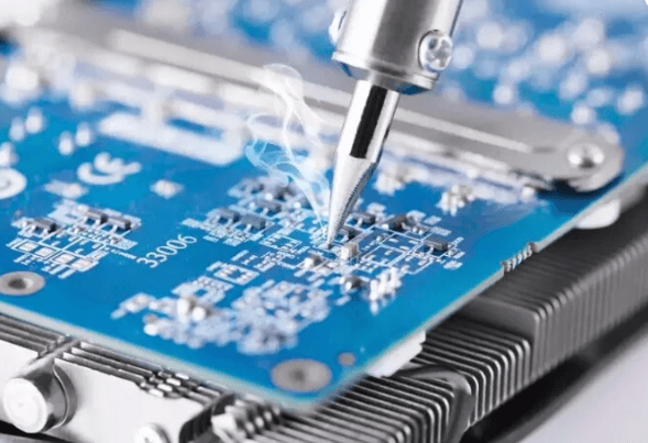
Heating: Heating the whole soldering part is heated, sustain about 1 ~ 2 seconds.
Feed the soldering wire: When solder circuit boards, the soldering points of the component are heated to a certain temperature, then can feed the solder wire to contact the solder pads.
Remove the soldering wire: When solder circuit boards, the wire is melted for a certain amount, immediately remove the wire in the direction of 45° to the left.
Remove the soldering iron: After the solder is melted in solder pads and the soldering parts, move the soldering iron to the upper right 45° to end the soldering.
Notes for circuit board soldering
- When solder circuit boards, the PCB shall first check its appearance to see whether there is any short circuit or open circuit, and then compare the schematic with the silkscreen layer of PCB to avoid any discrepancy between the schematic and PCB.
- The components are classified according to their size for the convenience of subsequent soldering.
- Before solder circuit boards, wear an anti-static ring and other anti-static measures to avoid electrostatic damage to components.
- The chips before solder circuit boards to ensure that the orientation of the chip is placed correctly.
- Distinguish positive and negative electrodes for LEDs, tantalum capacitors, and electrolytic capacitors.
- For crystal oscillator, passive crystal has no positive and negative requests, and generally only two leads, active crystal generally has four leads, should distinguish the positive and negative when solder circuit boards.
- For plug-in components, the pins of the components can be trimmed before soldering.
- If any component packaging error, installation problem, incorrect pad design, and other problems are found in the solder circuit boards process, record them in time for subsequent improvement.
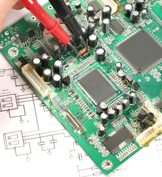
- After solder circuit boards should use a magnifying glass to check the solder joints, check whether there is a poor soldering or short circuit.
- After the completion of the circuit board soldering, the surface of the circuit board should be cleaned.
- To keep the iron head clean, the iron head is in a high-temperature state for a long time when solder circuit boards.
- The tin-plated parts of the components shall be heated evenly during solder circuit boards to avoid damage or hidden dangers that are not easily detected.
- Do not move the components when solder circuit boards. It is necessary to remove the tweezers after the solder is solidified, otherwise, it is easy to cause poor soldering.
- The evacuation of the iron should be timely, and the angle and direction of the evacuation are related to the formation of the solder joint.
-
The correct amount of solder. Generally, the diameter of the solder wire should be slightly less than the diameter of the solder pad.
-
The correct amount of flux should. Excessive use of rosin flux, after solder circuit boards, is bound to need to erase the excess flux, and prolong the heating time, reduce the solder circuit boards efficiency.
Circuit Board Soldering Skills
First, the correct use of electric soldering iron
Second, correct soldering sequence
Then, the method of manual soldering
What are the different solder circuit boards techniques?
There are various methods of soldering circuit boards. They are mainly divided into two different techniques: hard soldering and soft soldering.
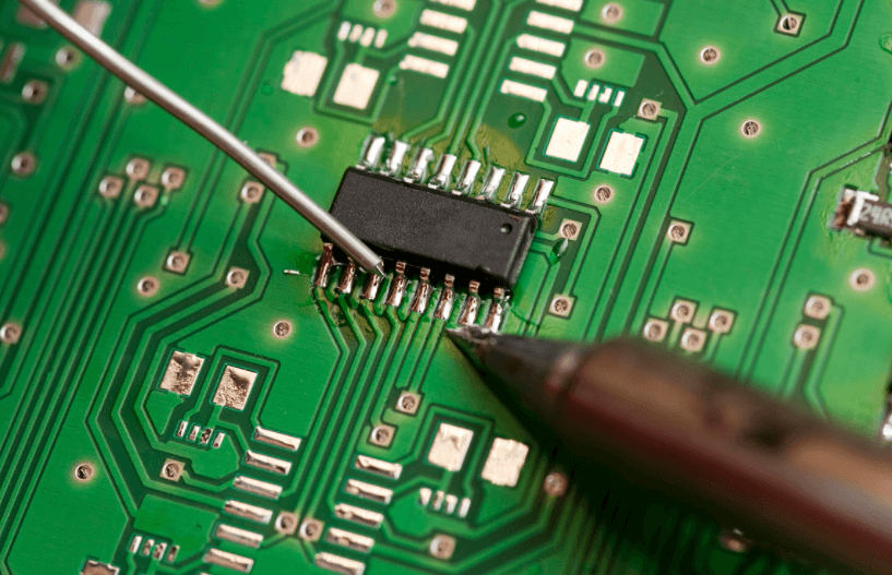
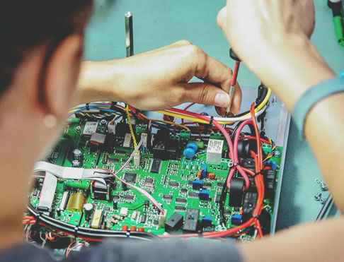
1. soldering pcb board- Soft soldering
Soft soldering is used to connect small components to a larger PCB. Of course, soldering pcb board is not simply melting the details but must use an additional step to connect the pieces to the board. In this case, this extra step is a filler metal, usually a tin-lead alloy.
The use of this alloy is critical in the soldering process because it acts as the glue between the component and the board, holding the two together firmly.
2. soldering pcb board – hard soldering
Hard soldering is a process that uses a solid solder to join two different metal components together. As a soldering pcb board process, hard soldering consists of two smaller sub-processes called silver soldering and brazing.