
Today we use radios, mobile phones, Wi-Fi, GPS, radar, and many other wireless devices almost every day. All of these systems depend on signals moving at different frequencies. But there are so many signals around us. Have you ever wondered how an RF system handles the right one without getting confused? The secret lies in the local oscillator. For newbies, this term might feel technical, but understanding it is very crucial. A small change in the oscillator frequency can cause problems with signal tuning. But if this term feels technical to you, worry not! In this guide, I will discuss everything you need to know about local oscillator essentials. You will know how it works, the formula, and applications. So let’s get started.
What Is a Local Oscillator & Why Is It Needed?
A local oscillator (LO) is an electronic circuit that produces a steady signal at a specific frequency. It is mainly used in RF systems and changes a signal from one frequency to another. The frequency produced by the oscillator is called the local oscillator frequency (fLO).
In simple terms, a local oscillator gives a controlled frequency that an RF system can use to process signals. Basically, RF systems often deal with very high-frequency signals. These high frequencies are difficult to filter, amplify, and process directly. That’s where the local oscillator comes in. It works with a mixer, another important RF component.
Together, they shift an incoming signal to a different frequency that is more convenient for the RF system to handle. Suppose a receiver picks up a signal at 100 MHz, but its main processing circuit is designed to work at a lower frequency. In this case, this high frequency can affect its performance. So, the local oscillator provides another frequency to the mixer.
This mixer combines the two signals and creates new frequencies. The receiver will then select the required frequency and continue processing the signal. That’s why local oscillators are needed in many RF systems. They produce a stable, accurate frequency so that RF systems continue to work.
How Does a Local Oscillator Work?
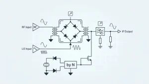
The working principle of the local oscillator is very straightforward. It works by producing a steady electrical signal at a specific frequency. It is a small part of an RF system that continuously creates its own frequency. The RF system selects this frequency based on what it needs to do with the incoming RF signal.
When a local oscillator produces a signal, it sends it to a component called a mixer. At the same time, the mixer also receives the incoming RF signal. The mixer puts these two signals together and creates new frequencies. However, keep in mind that the local oscillator does not change the information in the original signal. Instead, it just helps the system move that signal to another frequency. Let me explain with an example.
Suppose a receiver gets an RF signal at 100 MHz. However, its local oscillator produces a signal at 110 MHz. When these two signals meet in the mixer, the system gets a difference of 10 MHz (110 MHz − 100 MHz = 10 MHz). At the same time, a higher frequency of 210 MHz is also produced (110 MHz + 100 MHz = 210 MHz). Now the receiver has two frequency options. But it uses a filter and selects the 10 MHz signal because it is easier for the RF system to work with.
Local Oscillator Formula
Now you have a basic idea about what a local oscillator is and how it works. Right? Now it comes to understanding its formula. The local oscillator formula is used to find the new frequency produced when an RF signal and a local oscillator signal are mixed. When two different frequencies meet in a mixer, they produce new frequencies. The two most important ones are the sum of the two frequencies and their difference. In almost all RF systems, the difference frequency is the one the system uses. That’s why here we will discuss only that difference formula, which is:
fIF = |fLO − fRF|
Here:
- fIF = intermediate frequency
- fLO = local oscillator frequency
- fRF = incoming RF frequency
The formula simply means: take the LO frequency and the RF frequency, subtract one from the other, and use the positive answer. For example, imagine a radio receiver receives a signal at 100 MHz. The receiver uses a local oscillator that produces a 110 MHz signal. Now subtract the two:
110 MHz − 100 MHz = 10 MHz
So, the difference frequency is 10 MHz. This 10 MHz signal is called the intermediate frequency (IF) if the receiver is designed to use it as its IF.
However, you may wonder where this subtraction comes from and why we subtract the frequency. Basically, the mixer does not pass the two original frequencies through. When the RF signal and LO signal are combined, the mixing process creates new frequency components.
The two basic results are:
LO + RF = Sum frequency
LO − RF = Difference Frequency
Now, if we use the above example, you will get two possible frequencies.
110 MHz + 100 MHz = 210 MHz
and:
110 MHz − 100 MHz = 10 MHz
Therefore, the mixer can produce 210 MHz and 10 MHz as important output components. However, the receiver uses a filter to select the desired frequency. That frequency is usually lower because RF systems work well with it.
What is the Local Oscillator Frequency and How Can You Find It?
The local oscillator frequency (fLO) is the frequency produced by the local oscillator. As you know, a local oscillator is an electronic circuit. It produces a frequency that is sent to the mixer. The mixer combines it with incoming RF signals. After that, two other frequencies are generated, chosen by the receiver.
Sometimes you know the RF frequency and the IF you want. However, you do not know what frequency the local oscillator should produce. In that case, we can rearrange the above formula.
There are two cases.
First, if the local oscillator is higher than the RF frequency, such as in a high-frequency PCB, then you have to use the formula:
fLO = fRF + fIF
For example, if fRF = 100 MHz and fIF = 10 MHz
Therefore, using the formula above, you will get:
fLO = 100 + 10 = 110 MHz
So, a 110 MHz local oscillator will give you a 10 MHz difference when mixed with a 100 MHz RF signal.
The second case is when the local oscillator is lower than the RF frequency. In that case, the formula will be:
fLO = fRF − fIF
When you put values, you will get:
fLO = 100 − 10 = 90 MHz
So, a 90 MHz local oscillator can also produce a 10 MHz difference with a 100 MHz RF signal.
Types of Local Oscillators
Local oscillators are not always the same; they are designed differently depending on the RF system’s needs. Some of those types are mainly chosen for high-frequency stability. However, some oscillator types are useful when the frequency needs to be changed or controlled. Let’s take a look at the main types of local oscillators you can choose from.
-
Crystal Oscillator
A crystal oscillator uses a small piece of quartz crystal that produces a very stable frequency. The crystal naturally vibrates at a particular frequency when an electrical signal is applied to it. The circuit uses this natural vibration to create a steady electrical signal. Its frequency does not change easily because of small changes in temperature or other operating conditions.
-
LC Oscillator
An LC oscillator uses two main components: an inductor (L) and a capacitor (C). These two parts work together and create a resonant circuit. This resonant circuit produces an oscillating electrical signal at a particular frequency. The frequency of an LC oscillator mainly depends on the values of its inductor and capacitor. If these values are changed, the output frequency can also change. This becomes important when designing RF circuits through electronic contract manufacturing.
-
Voltage-Controlled Oscillator
A voltage-controlled oscillator (VCO) is one whose frequency alters with an applied control voltage. In simple words, change the control voltage, and the oscillator changes its frequency. This ability to change frequency electronically makes VCOs very useful in RF systems.
-
PLL-Based Local Oscillator
A PLL-based local oscillator uses a phase-locked loop (PLL) to generate a controlled and stable output frequency. A PLL compares the oscillator’s output with a stable reference signal and adjusts the oscillator when needed. This feedback process helps the system maintain the output frequency close to the desired value.
Common Challenges with Local Oscillators
A local oscillator might seem like a simple frequency source. However, its performance can affect the whole RF system. It must produce the correct frequency and keep that frequency steady. But sometimes, problems arise that must be controlled.
- Frequency Instability: One of the main challenges is to keep the oscillator at the same frequency. Actually, its frequency can change due to temperature, power supply fluctuations, and aging. Even a small change can cause the RF system to drift away from the required frequency.
- Phase Noise: A local oscillator ideally produces a clean signal at one exact frequency. In a real circuit, however, there are small unwanted variations around the main frequency. These variations are known as phase noise. This phase noise makes it difficult for an RF system to distinguish between nearby signals, which affects signal quality.
- Unwanted Frequencies: A local oscillator sometimes produces harmonics and spurious signals, along with its main output. These extra signals interfere with other parts of the RF system. If these signals reach sensitive parts of the RF system, they can cause interference or reduce the accuracy of signal processing.
- Temperature Changes: Temperature also affects oscillator performance. How? As the temperature around the circuit changes, the electrical properties of some parts also change. This causes the oscillator frequency to move away from its intended value.
Applications of Local Oscillator in RF Systems
RF systems often need to change, select, or generate specific frequencies. That’s why local oscillators are a major need for these systems. Let’s discuss the main areas in RF systems where local oscillators actually perform.
1- Radio Receivers
Radio receivers are one of the most common users of local oscillators. When a radio receives a signal from the antenna, the signal is often at a high frequency. It is not convenient to process directly. The local oscillator produces another frequency, and a mixer combines it with the received signal. This process creates a new frequency, often called the intermediate frequency (IF). The receiver now filters and amplifies this frequency more easily.
2- Wireless Communication
Local oscillators are also important in wireless devices such as mobile phones, Wi-Fi equipment, and so on. These devices require working with signals at controlled frequencies. As a result, they can send and receive information correctly. So, that is a local oscillator that converts the needed frequencies during transmission and reception. When a device gets a wireless signal, the local oscillator changes it to a frequency that the receiver can handle.
3- Radar Systems
Radar systems use radio waves to spot objects. They help determine how far away something is, which way it’s going, or whether it’s moving. Right? To do this accurately, the system needs very precise frequency signals. Local oscillators provide those stable frequencies needed to generate and process radar signals. They are used during both transmission and reception.
4- Satellite Communication
Satellite communication systems send signals over very long distances. They use high-frequency radio bands. These signals need to be converted from one frequency range to another before they can be transmitted or processed. That’s where the local oscillator comes in, performing these frequency conversions.
5- RF Test and Measurement Equipment
RF test equipment includes spectrum analyzers, signal generators, and network analyzers. These systems need accurate frequencies to test RF devices that use flexible PCBs. A spectrum analyzer uses frequency conversion inside its signal-processing path to examine signals. A stable oscillator will help it determine the signal’s frequency and characteristics.
6- Frequency Synthesizers
A frequency synthesizer is a circuit that generates a range of output frequencies. It does this using a stable reference frequency. Local oscillators are an important part of many frequency synthesizers. They become more important when the system needs to switch between different channels or frequencies. Suppose a wireless device operates at different frequencies depending on the selected channel. In this case, a synthesizer will adjust the local oscillator to produce the required frequency.
Conclusion
Whenever an RF system needs to operate across different frequencies, it requires a reliable way to generate and control them. That’s where local oscillators come into the scene. These oscillators are very small but are the most important part of these systems. They produce a steady frequency, and a mixer combines it with an incoming RF signal.
This process creates new frequencies, including the sum and difference of the two signals. The system can then select the required frequency and continue processing the signal. However, these oscillators come in different types to fit different needs. Each of those options has its own strengths, so the right choice depends on what the RF system is designed to do.