
There are many types of pcb board materials to choose from, such as metal PCBs, insulated metal substrates (IMS or IMPCB), metal core PCBs (MCPCB), aluminum composite boards, and aluminum substrates, etc. However, if heat dissipation is a consideration, then metal core or aluminum pcb is certainly a good choice. But if heat dissipation is a consideration, then the metal core pcb is the preferred choice. Metal PCBs offer more excellent heat dissipation than traditional FR-4 epoxy glass-based PCBs in the first place.
This is due to the 5 to 10 times higher thermal conductivity and 10 times higher thickness of conventional architectures. The exceptionally efficient heat transfer allows metal PCBs to use very light copper layers, thus reducing the cost and thickness of the solution. At the same time, the metal layer can be composed entirely of metal or a combination of glass fibers (FR-4) and metal.
Structure of Metal Core pcb
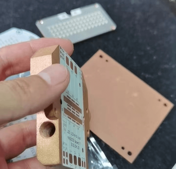
Metal PCBs consist of a dielectric layer with high thermal conductivity, a metal layer, and a copper film with high heat dissipation capability. The most widely used metal core pcb fabrication materials are aluminum and copper, and sometimes stainless steel. Metal core or aluminum pcb can subtract heat from high power components to facilitate heat transfer. So the purpose of using metal core pcb is to provide much higher thermal conductivity than FR-4.
Generally, the upper layer of the structure of China Metal Core pcb is formed by a thin copper film, which is etched like a conventional printed circuit board. The thickness of the thin copper film ranges from 1 ounce to 4 ounces. The innermost layer is a dielectric material whose function is to electrically isolate the metal layer from the copper film while allowing rapid heat transfer between the two layers. When the case of multi-layer MCPCB, must evenly distribute the layers concerning the inner metal layer. For example, in a 6-layer pcb, the metal layer is placed in the middle, the top 3 layers, and the bottom 3 layers.
We also need to note that the thermal PCB’s metal core can be aluminum-core PCB, copper-core PCB, or heavy copper PCB and stainless steel. However, the metal PCB material is very hard, and cutting the PCB into small pieces may cause problems. So we need to consider whether the chemicals in manufacturing will react to them when choosing metal PCB materials.
4 Advantages of Metal core pcb
Heat dissipation
This is one of the biggest advantages of metal core pcb. Its heat transfer rate is 8 to 9 times faster than that of FR-4 PCBs. If our PCBs need to be cooled quickly, then it is better to use metal PCBs instead of traditional FR-4 substrates. So the biggest advantage of metal core PCB is that it uses a special substrate material that increases the reliability of designs operating at higher than normal temperatures. metal core pcb design is actively absorbing heat from the location of hot running components to the opposite layer of the board, allowing for more efficient and safe heat dissipation.
Low cost
In addition to its thermal performance, aluminum has the advantage of being recyclable and low cost. When our led metal core pcb is discarded, we can recycle the metal from it. This also saves further production costs. At the same time, PCBs with metal substrates are lighter, longer-lasting and more conductive. Therefore, the manufacturing costs associated with PCBs with aluminum substrates can also be reduced. Aluminum PCBs are also a cost effective alternative to more expensive and bulky heat sinks. Aluminum is known to be a non-toxic and fully recyclable metal. The use of aluminum in metal PBCs helps protect our environment in the chain that connects producers and end consumers.
More Stability
China metal core pcb design will make the PCB more stable. Take the most used led metal core pcb as an example, it effectively solves the problem of heat dissipation for long time use of LED street lights and. In addition to ensuring high stability, aluminum is also very light, so it increases the strength and flexibility of the printed circuit board without increasing the weight.
Longer service life
Compared to the materials commonly used in PCB manufacturing, metal has a longer service life. Metal materials reduce the risk of accidental breakage of pcb during production, assembly and use.
Where are metal core PCBs used?
All of the above benefits make metal core PCBs ideal for a variety of applications, including
- Automotive, LED systems for street lighting
- Photovoltaic
- Backlight unit applications
- Motor/hybrid control applications
- Converters of energy
MCPCB surface mount components
The main feature of China metal core pcb designs is that they do not use plated through-holes. Metal core pcb fabrication typically uses surface mount components, one of the prominent features of the metal core pcb manufacturing process. If metal core pcb fabrication uses plated vias, the thick metal sheet on the underside of the laminate structure can cause a short circuit through the vias. Therefore, the metal core pcb design does not require heat dissipation through the through-hole. Due to this design, its cooling capacity is also improved.
By removing vias, metal core pcb manufacturers can move your boards more quickly. In most PCB manufacturing plants, this is a bottleneck process. Your 1-layer MCPCB then skips the chemical copper plating hole wall preparation step required for PTH processing and goes straight to circuit imaging after a quick drilling cycle. After that, your MCPCB will essentially follow the same process stages as any traditional FR4 design.
FR4 PCB vs MCPCB
| FR4 PCB | MCPCB | |
|---|---|---|
| Conductivity | FR4 has a low thermal conductivity, usually around 0.3W. | The heat conductivity of MCPCB is high, ranging from 1.0 to 4.0 watts, with 2.0 watts being the most frequent. |
| Plated through holes | Use Plated through holes | Surface Mount |
| Heat Release | Usually heat release with heat transfer through holes | Drilling, deposition, and plating operations are all eliminated when using MCPCB material because it dissipates its own heat. |
| Solder resist layer | FR4 PCB solder resist layer on top and bottom, usually green, blue, red, black, etc. | MCPCB solder resist layer only on the top, usually white LED board |
| Thickness | More flexible thickness range for FR4 PCBs, with various material combinations and layer counts available | MCPCB thickness variation is limited by the available backplane thickness and dielectric sheet thickness |
| Processes | Standard process for FR4 PCBs: countersunk holes, V-scoring, countersunk holes, routing, drilling | Use the same procedures for processing as FR4 (diamond-coated saw blades must be used for V-plates to increase the strain when cutting metal) |
How to use the base for PCB thermal management
One of the most common reasons for PCB failure is thermal stress. Excessive thermal stress can cause a PCB’s performance to degrade or possibly stop working entirely. As metal core pcb fabrication technology advances, the profile requirements of various components are getting smaller and smaller, and thermal stress is on the rise. As a result, effective thermal management in PCBs has become a critical aspect in keeping electronic devices from losing system functionality.
How does PCB thermal management work with metal cores with bases?
In most cases, the circuit and dielectric layers are placed on a base. Thermal management will typically use a metal core made of copper or aluminum.
If we do not implement effective thermal management, it will compromise the performance of any application. The transport of heat from the heat-generating component to the exterior heat sink is crucial. When a high thermal conductivity material like copper is utilized, heat transfer is improved. Copper-based bases are an alternative technology that, in the end, gives PCBs better thermal conductivity.
The copper in the metal core base improves thermal conductivity while lowering the component’s working temperature. As a result, it’s excellent for decreasing PCB thermal stress.
Use copper-based bases in the following scenarios.
- Single-sided, single-layer
- Copper filled laser thermal via matrix
- Double-sided chassis
Metal core pcb manufacturer manufacturer
There are a few things to think about when making a metal core pcbs. We will create an appropriate solution for your material as an example.
- Aluminum-filled 2-layer PTH boards (expensive pre-drilling/insulation filling/re-drilling operations are required to make plated through-holes that will not short out.)
- 2-layer or multilayer boards made using typical PCB techniques, but with a thermo-dielectric material instead of FR4 and a metal backing for heat transfer laminated on the bottom.
MCPCBs may be a good solution when numerous cooling LEDs are a design priority. The metal core pcb design may have some limitations, but the manufacturing process is not very different from that of other PCBs.
From MCPCB fabrication to assembly, we provide a one-stop-shop, with all production procedures inscribed on our self-developed app for online monitoring.