
Introduction
PCB assembly is the process of connecting every electrical component. To a printed circuit board, these components include resistors, transistors, diodes, and others. The PCB assembly can assemble mechanically or manually. PCB assembly and PCB manufacturing are two very different processes that are frequently confused. In contrast to PCB equipment assembly, which starts after PCB fabrication and is entirely about component placement? PCB manufacturing involves a wide range of procedures, including design and prototyping. Interestingly, hand soldering is not required when many PCBs are needed. Instead, producers create the PCBs using expert assembly machinery.
We will examine these little components that keep our gadgets functioning and thinking.
Let’s move ahead!
What is PCB Assembly Equipment?
PCB assembly equipment refers to the devices we use to combine printed circuit boards once they have been made. Each stage of the PCB assembly process needs a specific set of instruments to function correctly. And this is because there are various stages to the process. Each producer may have a different set of these steps or separate orders. However, most of the time, they must create functional circuit boards for the PCB assembly process.
Top 11 Must-Know PCB Assembly (PCBA) Tools
Primary top Must-Know PCB Assembly (PCBA) Tools are as follows:
1. Machine for Solder Paste Printing
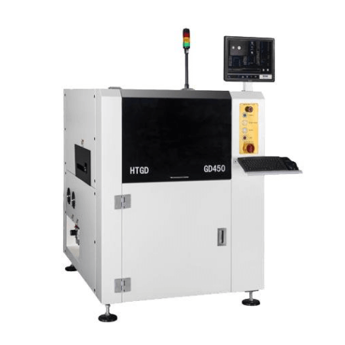
Printing solder paste onto the PCB is the primary function of this machine. It enables wave soldering and reflow soldering. The main components of this device are an extrusion, a soldered putty pump, and a pouring head.
The pumps that the solder paste has extruded from the extruder. And the dispensing head subsequently dispenses it onto the printed circuit board.
It is a guarantee that there are no dry spots or extra solder on the board; the solder paste delivery must be precise. Additionally, this machine can produce conductive ink, epoxy resin, and glue.
2. Soldering Iron (Soldering Station)
The two primary components of soldering iron are a heating section and a tip (popularly known as a temperature controller). Adjusting the power it provides, the tip temperature regulator regulates how hot the heater element gets. The heating element heats up as it melts in the interim.
It would help if you controlled both of these temperatures when soldering for your soldering iron to function effectively. And create joins of high quality without causing any harm to the boards or the components while in use.
3. Machine for Solder Paste Inspection (SPI)
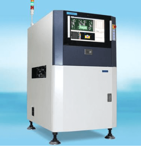
The SPI machine checks solder paste for flaws such as excess or missing tin. Solder paste that is not uniform, and color variations between different parts of the PCB.
The SPI machine is highly in demand with optical. It can be used along with scanning electron microscopes. Additionally, this device may look for probable particles on the die pad region and particles in the solder paste.
4. Machine for printing solder paste
The SPP machine utilizes a desktop copier/printer-style inkjet printer head to print solder paste onto the PCB. This device prints tiny amounts of solder paste onto a PCB equipment board before attaching components during assembly processes.
By using this method, manufacturers can manage their production processes. And get rid of any potential faults brought on by manual component placement during assembly activities.
5. Machine for dispensing glue
The glue dispenser applies an automated thin layer of glue to the PCB assembly equipment surface. Mainly integrated into the production line, the glue dispensing equipment runs automatically.
The raw material is initially loaded into the machine manually or automatically per the needs. Parameters are working according to the various types of boards. These are single-sided, double-sided, and multilayer boards.
Depending on your specifications, the glue will spray onto the PCB board surface at a specific speed. This is done through a nozzle with particular pressure and thickness. After that, it will operate without help when it obtains power from a 220V source.
6. Select-and-Place Device
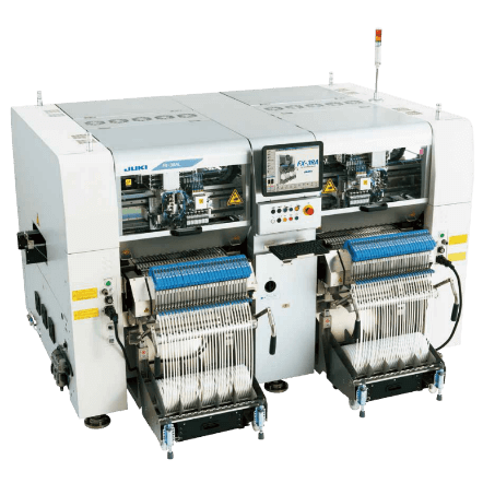
A pick-and-place machine is a tool that automatically and consistently places components onto the circuit board (PCB). To create the preferred outcome, the PCB must position correctly.
The pick-and-place for device objective is to quickly and precisely attach components to PCBs without endangering either the PCB or the components.
Any component can be positioned by the pick-and-place device on the PCB equipment. The procedures needed for each constituent determine how to put the pick-and-place device together.
For instance, an SMD pick-and-place machine will feature an X/Y table with highly accurate optical sensors to place the components correctly.
You will need a suction nozzle that handles these elements (passives and ICs) for more significant objects. Moreover, a highly accurate vacuum system must clutch down every component.
Thermocouples or infrared temperature sensors are crucial for spotting hot spots produced by high-power gadgets like LEDs and FETs. This feature guarantees that all parts are running at the proper temperature and guards against overheating-related harm.
7. Machine for Reflow Soldering
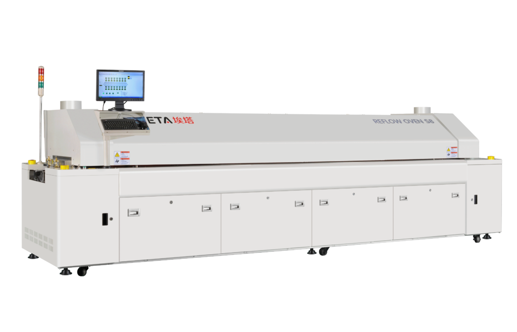
The quality of the finished product is greatly influenced by the reworked soldering machine, a part of the PCB assembly equipment process.
But it must be understood that the entire production process would completely halt without this device. Many people who begin out as technicians are frequently disregarded.
Making electrical connections between various components and other parts that have soldered together or coated with solder paste is the goal of the reworked soldering machine. These devices are also referred to as rework stations since they can be utilized for rework procedures.
However, there are numerous varieties of these machines on the market today. Most of them function by exerting pressure and heating parts at extremely high temperatures.
Technicians must know that specific safety precautions and guidelines must be followed when working with rework stations.
8. Wave Soldering Machine for PCBA (For Through-Hole Components)
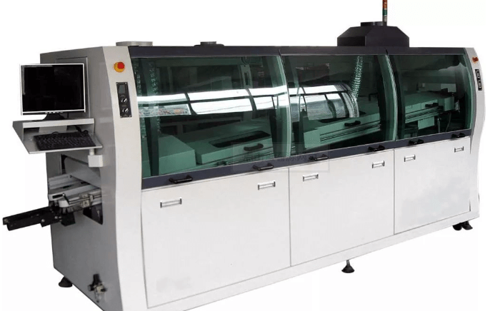
The most frequent method for soldering through-hole components onto a PCB is with a wave soldering machine. It’s one of the most straightforward, affordable, and adaptable techniques. It supports a high production volume and functions well with various technologies and materials.
A wave soldering machine flows molten solder over the components as they go through a temperature-controlled oven in a continuous wave.
Wave soldering equipment is made for high-throughput situations in mass manufacturing. What’s more, they must be durable enough to handle big boards with plenty of simultaneous soldering of components.
This implies that practically all wave soldering machines are created for boards between 1 in. and 2 in., with a maximum height of 0.185 in. or 5 mm over the outside of the panel when it enters the oven.
By modifying its temperature profile, a wave soldering machine may solder through-hole or surface-mount components. It is needed to handle the lead of a through-hole member and its body. Thus two distinct temperature zones are used by the enormous machines.
9. Autonomous Optical Inspection (AOI) Device
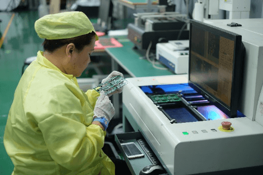
This technique is used to check for flaws, including missing pins or pads, feature misalignment, and potential contamination on component pads in components like BGAs, QFNs, and DIPs, as well as through holes. After assembly is complete, this method may also find short circuits between neighboring pins during testing.
This states that output is typically sent to an OPC computer, where specialists evaluate it and decide if the board should be rejected or, if feasible, upgraded before being delivered to clients.
10. Fixture for In-Circuit Testing (ICT)
PCBs were tested using the ICT fixture after assembly. For example, your phone charger or laptop computer has a power supply similar to the one used in this fixture, which also includes an indicator light that turns on when the board is turned up. When the board is switched on, the light will begin to blink, allowing you to check that all of your components are functioning correctly and that none of the board’s traces are shorting out.
An ICT fixture is vital for evaluating panels with surface-mounted parts since it affects the level of external connections required.
11. Fixture for the Functional Validation Test (FVT)
A functional validation test fixture is the best option to check your product’s functioning before going through your automated assembly line.
A piece of hardware called the FVT fixture enables you to connect parts or subassemblies, test those parts or subassemblies, and then evaluate the findings. These tests might be as basic as checking sure each component is in touch with other system members or as sophisticated as testing every component of a plan to make sure it works individually, collectively, and as a system.
It is required to check that all automated assembly systems are operating well and are not faulty before they leave the plant. FVT fixtures may occasionally be utilized after mechanical assembly systems have been installed.
Conclusion
You can successfully set up a PCB equipment assembly line with the help of the 11 PCBA pieces mentioned above of equipment. You can launch your own offline or online company if you can also create a basic circuit diagram and layout. It might be shocking to know how little money you can make by performing PCB assembly in large quantities. Just make sure that none of your family or friends is going hungry.